




A bore machined 0.05mm undersize will not accept its mating shaft. A gasket groove cut 0.1mm too shallow will leak under pressure. A mounting hole drilled 0.5mm out of true position will prevent a fastener from ever seating correctly. None of these are surface defects. A metal part can look flawless, no scratches, no discoloration, no visible damage, and still fail completely because its actual geometry does not match what the engineering drawing specifies. That is a fundamentally different inspection problem than catching a scratch or a stain, and it is exactly the problem 3D machine vision was built to solve for metal parts.
This distinction matters more than it might seem. Surface defect detection asks whether a part looks correct, the focus of most metal defect detection use cases. Dimensional inspection asks whether a part measures correctly, whether its bores, flatness, weld profiles, and tolerances actually match the CAD model it was supposed to be manufactured from. For cast, forged, machined, and welded metal components, that second question is often the one with real consequences: a part that passes visual inspection can still be scrapped, returned, or cause an assembly failure months later if its geometry was never actually verified.
This guide covers the 3D vision technologies used for dimensional inspection of metal parts, how they compare to traditional coordinate measuring machines, what accuracy is actually achievable, and where this technology fits on a real production line.
Why Metal Parts Demand Dimensional Inspection, Not Just Surface Inspection
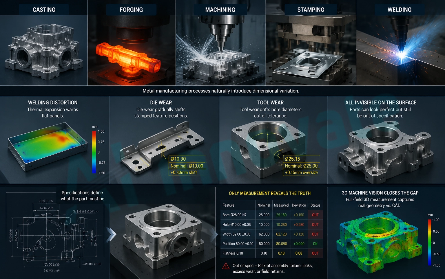
Metal manufacturing processes, casting, forging, machining, stamping, and welding, all introduce dimensional variation as a natural byproduct of the process itself. Thermal expansion during welding warps flat panels. Die wear gradually shifts stamped feature positions.
Tool wear on a CNC lathe slowly drifts bore diameters out of tolerance long before the tool visibly needs replacement. None of these failure modes are visible on the surface. They only show up when someone actually measures the part against its specification, which is precisely the gap 3D machine vision closes for metal components specifically.
The 3D Vision Technologies Used for Metal Part Inspection
Several distinct optical technologies are used to capture the three-dimensional geometry of a metal part, each with real trade-offs for accuracy, speed, and suitability to different metal surface finishes, extending the broader 2D vision vs 3D vision systems for inspection comparison specifically into dimensional measurement on metal.
Structured Light Scanning
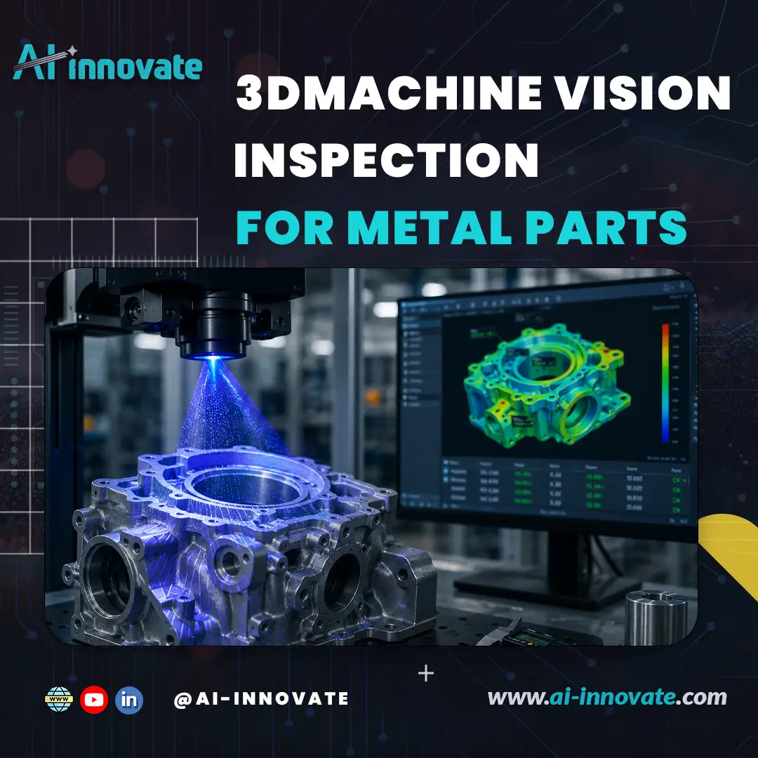
Structured light systems project a pattern, typically stripes or a grid of dots, onto the part surface and reconstruct its shape from how that pattern distorts across the geometry. This produces a dense point cloud well suited to complex freeform surfaces on cast and machined parts, and blue-light variants in particular deliver strong accuracy on parts up to roughly 500mm in size.
Laser Triangulation
A laser triangulation sensor projects a line onto the part and measures how that line’s position shifts as it crosses surface geometry, calculating a height map from the displacement. This technology handles reflective and dark metal surfaces better than most alternatives, making it a common choice for weld bead inspection, gap-and-flush measurement, and surface profiling at high speed on a moving line.
Photogrammetry
Photogrammetry determines part geometry by analyzing multiple images captured from different angles, reconstructing three-dimensional shape through triangulation across those views. It scales more effectively to larger parts than structured light or laser triangulation, though typically at a lower accuracy band, making it a common choice for large fabricated assemblies rather than small precision components.
Time-of-Flight Sensors
Time-of-flight cameras calculate depth by measuring how long light takes to reflect back from a surface, offering faster but lower-resolution 3D capture. This makes them well suited to robotic bin picking and large-object guidance, where millimeter-level accuracy is sufficient and speed matters more than micron-level precision.
Accuracy by Technology: What the Numbers Actually Show
Accuracy varies meaningfully by capture technology, part size, and surface characteristics, and understanding these bands matters when specifying a system for a real tolerance requirement.
| Technology | Typical Accuracy | Best Suited For |
|---|---|---|
| Blue-light structured light | 5-20 microns | Parts up to ~500mm, complex freeform surfaces |
| Laser triangulation | 10-50 microns | Reflective or dark metal surfaces, weld profiling |
| Multi-view photogrammetry | 20-100 microns | Larger parts and assemblies |
| 2D vision (telecentric lens) | 10-50 microns (linear) | Length, width, diameter on a single visible plane |
The pattern worth noting: structured light and laser triangulation both deliver production-relevant accuracy at line speed, but neither matches a coordinate measuring machine on the tightest tolerance bands, a trade-off covered in more detail below.
GD&T Verification: How 3D Vision Actually Checks Tolerance
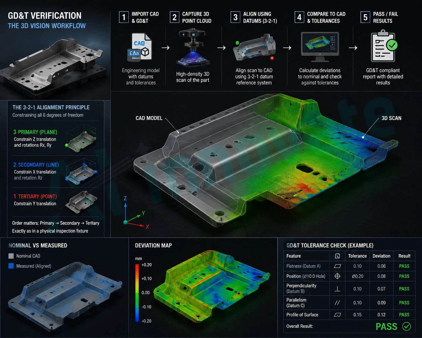
Geometric dimensioning and tolerancing, or GD&T, verification is where 3D vision moves from simply capturing shape to actually validating a part against engineering specification. The process imports the part’s CAD model along with its embedded datum features and their priority order, then aligns the captured scan to that model using a reference point system.
For sheet metal and machined parts, this commonly follows a 3-2-1 principle: three primary reference points, two secondary, and one tertiary, constraining all six degrees of freedom before any tolerance comparison happens. Only after this alignment, primary datum simulated first, then secondary, then tertiary, exactly as a physical inspection fixture would perform it, are deviations between the measured surface and the nominal CAD surface calculated and compared against the tolerances called out on the engineering drawing. This is what separates genuine GD&T verification from a simple visual pass or fail check.
3D Vision vs CMM for Metal Parts
Coordinate measuring machines remain the reference standard for dimensional metrology, and understanding where each technology genuinely fits avoids both over-investing in equipment a line does not need and under-specifying a system that cannot deliver the accuracy a part actually requires.
| Factor | CMM | 3D Vision |
|---|---|---|
| Accuracy | ±1-3 microns (lab), ±5-10 microns (shop floor) | ±10-100 microns typical |
| Speed | 30-60 minutes per part | Milliseconds per cycle |
| Throughput | Sample-based inspection | 100% inline capable |
| 3D Capability | Full 3D including internal features | Surface geometry only |
| GD&T | Full compliance, ISO 10360 traceable | Limited to surface-visible features |
| Contact | Contact (may mark soft surfaces) | Non-contact |
| Investment | $100K-$500K+ | $10K-$100K per station |
In practice, the strongest quality strategies rarely choose one exclusively. A CMM validates the process during setup and first-article inspection, confirming what a genuinely correct part actually measures, while 3D vision then monitors every part in production, flagging drift before it produces an out-of-tolerance unit. The CMM defines “good.” The vision system makes sure every part continues to match it.
What Real Research Shows: Benchmarking 3D Scanners on Metal Parts
Independent, peer-reviewed research has directly tested this technology against metal parts rather than idealized lab samples. One study measured a purpose-built GD&T test part manufactured in 17-4PH stainless steel using selective laser melting, comparing five different optical measurement systems based on laser triangulation, conoscopic holography, and structured light against a coordinate measuring machine reference.
The researchers found that two portable systems, handheld laser triangulation and structured blue-light scanners, delivered the strongest combination of speed and dimensional accuracy for scanning additively manufactured metal parts, confirming that these technologies hold up on real metal surfaces and real GD&T requirements, not just idealized test targets.
Common Metal Part Applications for 3D Vision
The applications where 3D vision earns its value on metal parts are almost entirely dimensional and geometric, not cosmetic.
- Casting and forging verification against CAD, confirming a part’s actual shape matches its digital model within specified tolerance before it moves further down the line.
- Weld bead profile and volume measurement, verifying bead height, width, and volume meet specification on structural and pressure-critical welds.
- Warpage, flatness, and coplanarity checks, catching thermal distortion on stamped, welded, or heat-treated panels before assembly.
- Bore diameter, thread pitch, and gear tooth geometry verification, confirming precision machined features fall within the tolerance a mating part actually requires.
- Gap and flush measurement, verifying panel and component alignment in assemblies where fit and finish carry functional as well as cosmetic importance.
Where 3D Vision Fits Into a Metal Production Line
- Station placement. Position inspection immediately after the operation most likely to introduce dimensional variation, so drift is caught before additional value gets added to a non-conforming part.
- Part presentation. Use robots, conveyors, or indexing fixtures to present parts in a consistent, repeatable orientation, since inconsistent positioning introduces measurement variability unrelated to actual part quality.
- Reject handling. Automated diverters or reject bins remove non-conforming parts without stopping the line, maintaining throughput while segregating suspect material.
- Data integration. Connect inspection results to a manufacturing execution system for statistical process control and traceability, so a drifting process gets corrected during the shift that produced it rather than discovered later.
- Calibration and maintenance. Establish regular calibration intervals; lens cleaning and lighting verification keep measurement confidence stable over time, the same discipline that underlies computer vision in metal quality control broadly.
How AI-Innovate Powers 3D Vision Inspection for Metal Parts
Dimensional inspection for metal parts combines genuine technical difficulty, reflective surfaces, tight tolerances, and CAD-referenced comparison, with real production consequences when it is skipped or done inconsistently.
AIxEye: Real-Time Detection Across Surface and Dimensional Checks
AIxEye performs the visual inspection layer that catches surface-level issues alongside dimensional checks, giving a single inspection pass visibility into both how a metal part looks and how it measures, rather than requiring two entirely separate systems for what is often one production checkpoint.
AIxAm: Purpose-Built for 3D Surface and Geometry Inspection
AIxAm is built specifically for the 3D geometric and surface measurement challenges covered throughout this guide, comparing captured part geometry against CAD reference models to verify dimensional tolerance on castings, machined features, and weld profiles, the exact kind of GD&T-referenced verification that separates dimensional inspection from simple visual defect detection.
AIxCore: Edge Processing for Inline Measurement Speed
AIxCore handles the on-site inference that keeps 3D measurement fast enough to run inline at production speed, processing scan data locally so a dimensional deviation gets flagged and acted on immediately rather than after a delay that lets an out-of-tolerance part continue down the line.
Final Thoughts
3D machine vision inspection for metal parts solves a genuinely different problem than surface defect detection: verifying that a part’s actual geometry, its bores, flatness, weld profiles, and critical tolerances, matches what the engineering drawing specifies, catching the dimensional drift that visual inspection alone was never designed to see.
The manufacturers getting real value from this technology are not replacing their CMMs. They are using coordinate measuring machines to define what a correct part actually measures, then deploying 3D vision to verify that every part in production continues to match that standard, at a speed and volume no CMM could sustain on its own. For metal parts where a dimensional failure often surfaces only after assembly, or after a customer complaint, that shift from sampling to full inline dimensional verification is where the real return sits.
Frequently Asked Questions
What is the difference between 3D vision inspection and surface defect detection for metal parts?
Surface defect detection identifies visual flaws like scratches, discoloration, or contamination. 3D vision dimensional inspection measures a part’s actual geometry, bores, flatness, weld profiles, tolerances, against its CAD model, catching failures that are invisible on the surface but prevent a part from functioning correctly.
How accurate is 3D machine vision compared to a coordinate measuring machine?
CMMs typically achieve 1 to 3 microns of accuracy in a lab environment, while 3D vision technologies generally deliver 10 to 100 microns depending on the specific method, part size, and surface characteristics. CMMs remain the reference standard for the tightest tolerances, while 3D vision trades some accuracy for dramatically faster, non-contact, 100% inline measurement.
Which 3D vision technology works best on metal parts?
Laser triangulation generally performs best on reflective or dark metal surfaces, while structured light scanning excels on complex freeform geometry like castings and machined parts. Peer-reviewed benchmarking on additively manufactured stainless steel parts found handheld laser triangulation and structured blue-light scanners delivered the strongest combined accuracy and speed for metal components specifically.
Can 3D vision fully replace a CMM for dimensional inspection?
Generally no, particularly for internal features like bores and channels that require direct line of sight, and for the tightest GD&T tolerances. Most effective quality strategies use a CMM to validate the process during setup and first-article inspection, then deploy 3D vision to monitor every part during production.
What is GD&T verification in the context of 3D vision?
GD&T, or geometric dimensioning and tolerancing, verification compares a scanned part’s geometry against its CAD model using a defined reference point system to align the two, then measures deviations against the specific tolerances called out on the engineering drawing, following the same datum-simulation principles a physical inspection fixture would use.
What metal manufacturing processes benefit most from 3D vision inspection?
Casting, forging, welding, and precision machining benefit significantly, since each process introduces dimensional variation, thermal warpage, die wear, tool drift, weld distortion, that surface inspection alone cannot detect and that only shows up when a part’s actual geometry is measured against specification.
Sources
Ai-Innovate uses only high-quality sources, including peer-reviewed studies, to support the facts within our articles.
- AMD Machines. (2025). Dimensional Inspection: CMM vs Vision vs Laser Scanning. https://amdmachines.com/blog/dimensional-inspection-with-cmms-and-vision/
- iFactory AI. (2026). Dimensional Measurement and GD&T Verification with AI 3D Vision. https://ifactoryapp.com/ai-vision-camera/dimensional-measurement-gdt-verification-ai-3d-vision
- Ontiveros, S., Yagüe-Fabra, J. A., Jiménez, R., et al. (2018). Analysis of Modern Optical Inspection Systems for Parts Manufactured by Selective Laser Melting. Sensors, 18(6), 1876. https://www.ncbi.nlm.nih.gov/pmc/articles/PMC7308957/