Smart Cameras vs. PC-Based Machine Vision Systems

Smart Cameras vs. PC-Based Machine Vision Systems

Every machine vision project starts with the same question, and rarely lands on the same answer twice: does this problem need a compact, all-in-one smart camera, or does it need the scalability and raw compute of a PC-based system? Get the answer wrong and the consequences are not subtle. Choose a smart camera for a problem that later needs eight synchronized cameras and deep learning inference, and you have painted yourself into a corner with a single-socket device that cannot scale. Choose a full PC-based rig for a single, well-defined barcode-reading station, and you have bought far more flexibility, cost, and complexity than the problem ever required.

This is not a new debate. Machine vision engineers have been arguing the merits of each approach since smart cameras first became powerful enough to challenge PC-based systems for real industrial work, and the fundamental trade-offs identified decades ago still hold, even as the hardware on both sides has become dramatically more capable. What has changed is the range each architecture can now cover: smart cameras today embed GPUs with hundreds of CUDA cores and multiple gigabytes of memory, while PC-based systems now scale down to edge accelerators nearly as compact as the smart cameras they used to be categorically faster than.

This guide covers what genuinely distinguishes the two architectures, where each one wins and falls short, what they cost in 2026, and how to actually decide between them for a specific application rather than defaulting to whichever one a vendor happens to sell.

What Actually Distinguishes These Two Architectures

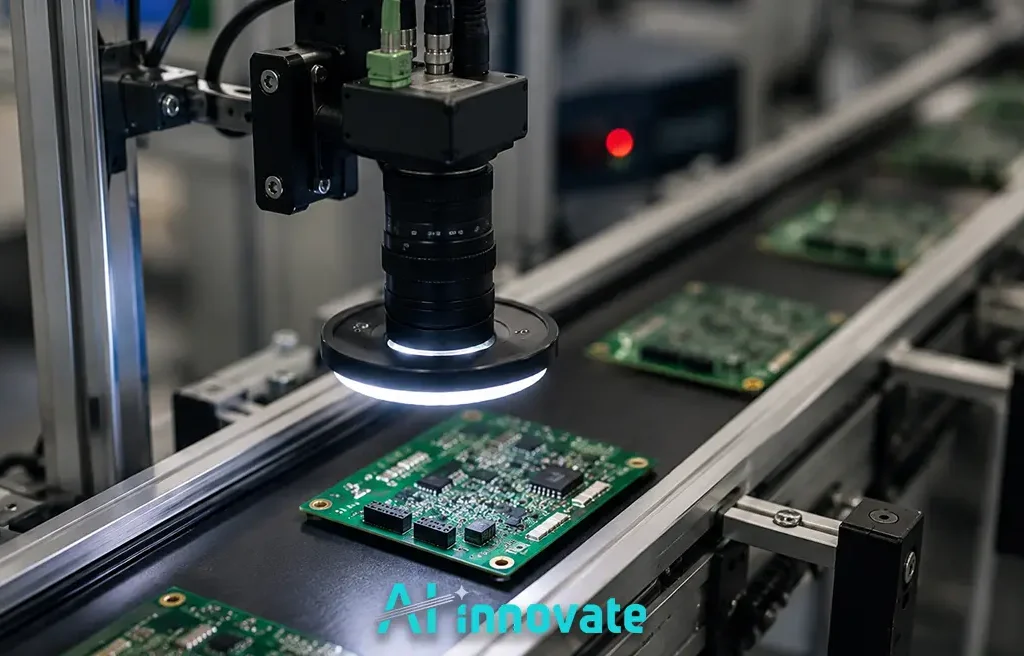
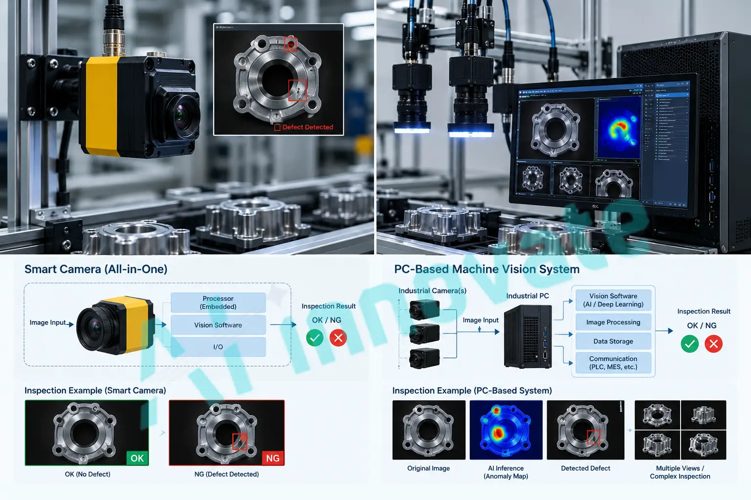
A smart camera is a self-contained unit. The imager, the processing intelligence, and the input/output capability all live inside a single housing. Because that format resembles an intelligent sensor more than a traditional camera, these devices are sometimes called vision sensors, though a true smart camera generally offers more programmable flexibility than a fixed-function vision sensor.

A PC-based system separates those functions. A camera, whether connected directly via USB, GigE, or CameraLink, or through a frame grabber board, feeds image data to a separate processor, typically an industrial PC or a dedicated vision controller. That separation is the entire architectural distinction, and nearly every practical trade-off between the two approaches traces back to it.

A third category sits between these two extremes: the embedded vision computer. This is a stand-alone box with its own frame storage and processing intelligence, similar in spirit to a PC-based system, but with the camera tethered to the unit rather than built into it, and often with more limited, application-specific flexibility than a full PC. It can typically handle multiple camera inputs, which a single smart camera cannot, while avoiding some of the complexity a full PC deployment carries.
Smart Cameras: Strengths and Real Limits

Where Smart Cameras Win

Smart cameras are generally less expensive to purchase and set up than an equivalent PC-based solution, since the camera, lens, processing, and often lighting all ship as one integrated unit rather than components sourced from separate vendors. That unified packaging also makes them notably easier to integrate into a manufacturing environment: fewer cables, fewer points of failure, and a physically compact footprint that matters when mounting space is tight or a camera needs to move with a robotic arm.
Reliability follows the same logic. With no fan, no hard drive, and lower internal operating temperatures than a full PC, smart cameras tend to run more reliably in harsh production environments, and their software tools are typically simpler, point-and-click configuration with pre-packaged algorithms rather than a full development environment. Because the processor sits directly at each inspection point, a network of smart cameras also distributes computational load naturally: only the inspection result needs to travel back to a central system, not the raw image data, which keeps bandwidth and central processing requirements low even across many inspection stations. 

Where Smart Cameras Fall Short

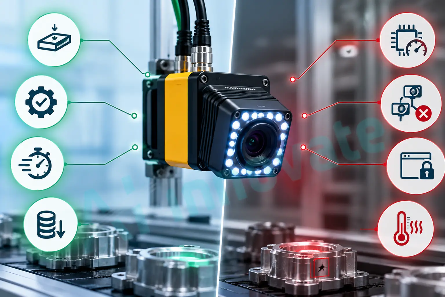
The same self-contained design that makes smart cameras simple also caps their ceiling. Computational power cannot be exceeded once the unit is purchased. A smart camera is a single-socket device, meaning one camera per unit, which makes multi-camera applications expensive to scale compared to a PC-based system that can often manage four or more cameras through a single frame grabber. If a smart camera cannot handle an application as originally specified, there is generally no path to migrate that setup to a more powerful platform without starting over on both hardware and software.
Smart cameras also tend to offer a fixed, vendor-specific software ecosystem rather than the choice of third-party tools a PC-based system allows, and very high-speed or high-resolution applications, the kind found on fast beverage or can lines running well above a thousand parts per minute, frequently exceed what a smart camera’s onboard processing can sustain for full 100 percent inspection coverage.
Smart Cameras

PC-Based Systems: Strengths and Real Limits

Where PC-Based Systems Win

Flexibility is the defining advantage. A PC-based system can use line-scan or area-scan cameras interchangeably, run third-party software packages rather than being locked to a single vendor’s tools, and scale computational power simply by upgrading the PC itself. Because the platform is fundamentally open, its cost-to-performance ratio has historically been difficult for any closed, purpose-built device to match, and that gap widens further for applications requiring the heaviest processing: high-resolution sensors, complex deep learning models, or many simultaneous camera feeds.
PC-based systems also handle the scenario every experienced vision engineer eventually runs into: a project’s true requirements turning out to be more demanding than initially scoped. Because the PC platform has headroom built in by design, that kind of scope creep is a software or component upgrade rather than a full system replacement.

Where PC-Based Systems Fall Short

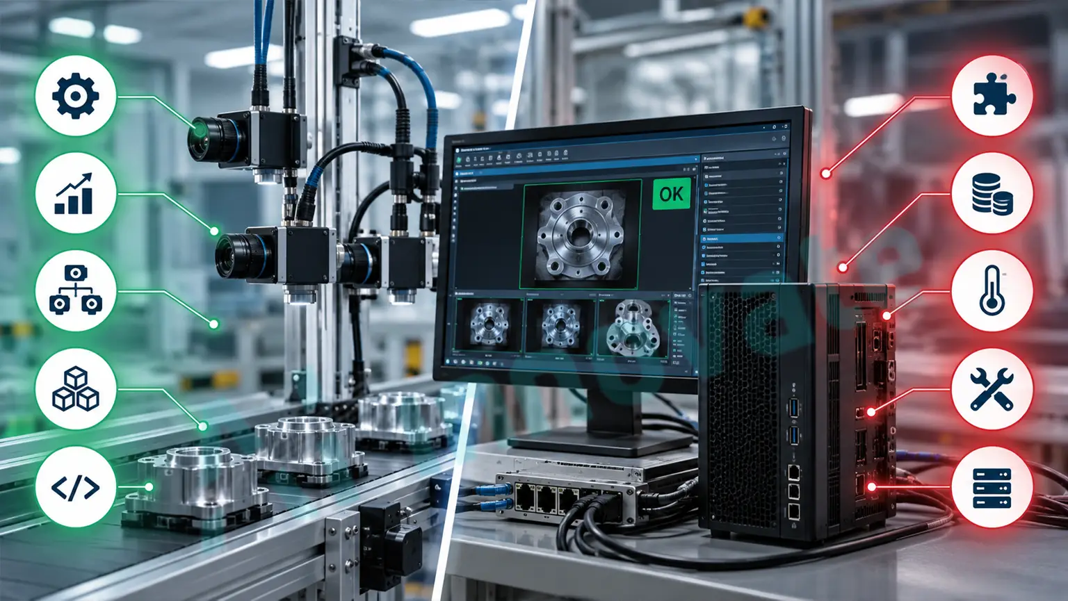
That flexibility comes at a real cost in complexity. A PC-based system typically involves a camera, a frame grabber or interface card, and a PC, often from three different manufacturers, which introduces compatibility, driver, and partial feature-support issues that a single-vendor smart camera simply does not encounter. Some very specific low-level camera functions, adjusting the electronic shutter frame by frame, for instance, are straightforward on a smart camera with direct sensor control and can be genuinely difficult to implement cleanly through a multi-vendor PC stack.
PC-based systems also carry more physical footprint and more points of potential failure: fans, hard drives, and higher operating temperatures that can degrade components over time in a harsh industrial environment. And despite the flexibility PC-based systems offer, they generally require real computer skills to configure and maintain, a meaningfully higher bar than the largely turnkey setup smart cameras are designed around.
PC-Based Systems

The Architecture Trade-off at a Glance

Factor PC-Based Smart Camera
Flexibility Excellent, open platform, third-party software Limited, vendor-specific toolset
Ruggedness Lower, more moving components High, fewer points of failure
Physical Footprint Multi-box system, more cabling Compact, single all-in-one unit
Functionality Expandable Fixed at time of purchase
Processing Power Expandable via hardware upgrade Fixed, capped by onboard hardware
Multi-Camera Scaling Efficient, one frame grabber handles several cameras Costly, one camera per unit
Ease of Setup Requires computer and integration skill Largely point-and-click
Typical Cost Higher, especially at scale Lower for single or few inspection points

Real-World Cost Ranges in 2026

A single smart-camera inspection station, including lighting, optics, and integration, typically runs in the $10,000 to $50,000 range. Engineered PC-based systems, particularly those involving 3D sensors, deep learning software, multiple cameras, fixturing, and full line integration, commonly run $50,000 to $250,000 or more. That gap is not simply markup. It reflects the genuine difference in engineering complexity between a turnkey single-camera device and a custom multi-camera system with dedicated processing hardware, custom software, and full line integration.
It is worth noting that despite the rise of capable smart cameras, demand for high-end PC-based imaging hardware, frame grabbers and dedicated acquisition cards among them, has continued to grow rather than shrink. The explanation is straightforward: as smart cameras absorbed the simpler end of the application spectrum, high-resolution and high-frame-rate applications that exceed smart camera capability have grown to fill the gap, keeping demand for hardware costing well over $10,000 buoyant even as entry-level vision costs have fallen dramatically.

How Modern Smart Cameras Have Closed the Gap

The performance ceiling on smart cameras has moved dramatically since the earliest devices in this category, which relied on lower-performance processors constrained by size and heat dissipation. Modern smart cameras routinely embed ARM or DSP processors, and increasingly GPU accelerators as well. The Cognex In-Sight 3800, for example, integrates 4 GB of onboard memory with optional liquid-lens autofocus, while Photoneo’s MotionCam-3D smart camera includes an NVIDIA Pascal GPU with 256 CUDA cores for real-time 3D depth computation, a level of onboard compute that would have required a dedicated PC just a few years ago. Some smart cameras now even use AI-driven scoring to automatically configure their own lighting setup, adjusting internal LED configuration to optimize image quality without manual tuning.
This does not eliminate the fundamental trade-off between the two architectures, but it has meaningfully shifted where the line sits. Applications that once categorically required a PC-based system purely for processing headroom increasingly fit within a modern smart camera’s capability, which is precisely why the decision has to be based on the specific application’s actual requirements rather than an assumption about what smart cameras can or cannot do.

When to Choose Each Architecture

  • Choose a smart camera when the application is well-defined and stable, involves a single camera or a small number of independent inspection points, needs to be deployed quickly with minimal integration engineering, and is unlikely to require significantly more processing power or functionality later.
  • Choose a PC-based system when the application requires multiple synchronized cameras, involves heavy computational demand like deep learning inference on high-resolution images, needs the flexibility to evolve significantly as requirements are refined, or requires third-party software integration a closed smart camera platform cannot support.
  • Consider a hybrid approach when different inspection points on the same line have genuinely different requirements. It is common and often the most cost-effective choice to deploy smart cameras at simple, well-defined checkpoints while reserving PC-based compute for the one or two stations on a line that genuinely need it, rather than forcing every station onto a single architecture.

The Hybrid Middle Ground: Embedded Vision Computers

For applications that need more than a single smart camera can offer but do not require the full flexibility of an open PC platform, embedded vision computers occupy a genuine middle ground. These are stand-alone units with their own frame storage and processing intelligence, generally supporting multiple tethered cameras, but built around a more limited, application-specific set of fixed routines than a full PC deployment. This makes them a reasonable fit for applications with predictable, well-understood requirements across a handful of camera positions, where a full PC-based system would represent more engineering flexibility than the problem actually calls for.

How AI-Innovate Works Across Both Architectures

The choice between smart camera and PC-based hardware determines where processing physically happens, but it should not determine what defect detection capability a manufacturer has access to. A well-designed inspection platform needs to run effectively on whichever architecture actually fits the line.

AIxEye: Detection That Runs on Either Architecture

AIxEye delivers real-time visual inspection whether deployed on a compact smart camera handling a single, well-defined inspection point or on a PC-based system managing multiple synchronized cameras and heavier processing demand, adapting to the compute envelope actually available rather than requiring one specific hardware architecture.

AIxAm: Dimensional Inspection Where the Application Demands It

AIxAm supports the 3D surface and geometry inspection use cases that most often push a deployment toward PC-based or GPU-equipped smart camera hardware, comparing captured geometry against CAD reference models for the dimensional verification applications covered in more depth in our 2D vision vs 3D vision systems comparison.

AIxCore: Edge Processing Sized to the Hardware Available

AIxCore handles the on-site inference layer regardless of whether that inference runs on a GPU-equipped smart camera or a dedicated PC-based edge system, an architecture decision covered in detail in our edge AI deployment guide, which walks through sizing compute correctly for the actual throughput and latency a line requires.

Final Thoughts

Smart cameras and PC-based systems represent two genuinely different points on the same design continuum, not a strictly better and worse option, and the right choice depends entirely on how well-defined the application is, how many cameras it requires, and how much computational headroom it genuinely needs both today and as requirements evolve.

The manufacturers who get this decision right are not the ones defaulting to whichever architecture their integrator sells by default. They are matching the architecture to the actual shape of the problem: a smart camera for a stable, single-point inspection task where simplicity and reliability matter most, a PC-based system where scale, flexibility, or heavy computation genuinely justify the added complexity, and increasingly a deliberate hybrid of both across a single production line where different stations have genuinely different requirements. Getting that match right the first time avoids both the smart camera that outgrows its capability in six months and the PC-based system that was never actually needed. For a deeper look at how to plan a vision deployment from the ground up, our Vision System Guide for Manufacturers covers the budget and decision framework that should come before this specific hardware choice.

Frequently Asked Questions

What is the main difference between a smart camera and a PC-based machine vision system?

A smart camera integrates the imager, processing, and input/output capability into a single self-contained unit. A PC-based system separates the camera from the processing, connecting one or more cameras to a separate industrial PC or vision controller, which offers greater flexibility and scalability at the cost of more integration complexity.

Not necessarily anymore. Modern smart cameras increasingly embed GPU accelerators and several gigabytes of memory, closing much of the performance gap that once existed. However, smart cameras remain fixed in processing power once purchased and are single-camera devices, while PC-based systems can scale processing and camera count as requirements grow.

A single smart camera station, including lighting, optics, and integration, typically costs $10,000 to $50,000. Engineered PC-based systems with multiple cameras, 3D sensors, or deep learning software commonly run $50,000 to $250,000 or more, depending on complexity.

Not efficiently on its own, since a smart camera is inherently a single-socket device with one camera per unit. Applications requiring several synchronized cameras are generally better served by a PC-based system, which can typically manage four or more cameras through a single frame grabber or interface.

An embedded vision computer is a stand-alone processing unit with its own frame storage and intelligence, similar to a PC-based system, but with the camera tethered externally rather than integrated into the unit. It generally supports multiple camera inputs like a PC-based system, while offering a more limited, application-specific set of functions than a full open PC platform.

They can and often should coexist. It is common and frequently the most cost-effective approach to deploy smart cameras at simple, well-defined inspection points on a line while reserving PC-based compute for the one or two stations that genuinely require heavier processing or multi-camera synchronization.

Ai-Innovate uses only high-quality sources, including peer-reviewed studies, to support the facts within our articles.

  1. Zuech, N. AIA (Association for Advancing Automation). Smart Cameras vs. PC-Based Machine Vision Systems. https://www.automate.org/vision/industry-insights/smart-cameras-vs-pc-based-machine-vision-systems
  2. Wevolver. (2026). Top Vision Systems for Manufacturing in 2026. https://www.wevolver.com/article/top-vision-systems-for-manufacturing-in-2026
  3. Relling Systems. (2026). Best Machine Vision Systems for Inspection (2026): Compared. https://rellingsystems.com/resources/robots/machine-vision
Vision System Guide for Manufacturers 2026 Guide

Vision System Guide for Manufacturers: 2026 Guide

Most vendors quote vague estimates for a vision system, and 68 percent of manufacturers report budget overruns on their first deployment as a result, primarily because integration complexity and ongoing operational costs get underestimated from the start. That is not a technology problem. It is a planning problem, and it is entirely avoidable once you know what questions to ask before you talk to a single vendor.

This guide is the starting point, not the deep dive. It answers the questions that come before camera specs and model architecture: what kind of vision system your use case actually needs, what realistic budget tiers look like, whether to build, buy, or bring in an integrator, and where deployments typically go wrong. Once you have those answers, this guide points you to the more technical resources on specific pieces, sensor selection, edge deployment, defect coverage, that go deeper on each decision.

Start With the Use Case, Not the Technology

The single most common mistake in vision system planning is starting with a technology preference, “we want 3D” or “we want AI,” before defining what the system actually needs to accomplish. Vision applications in manufacturing fall into a handful of distinct categories, and the category determines nearly every downstream decision.

  • Inspection and defect detection. Identifying scratches, contamination, dimensional flaws, or missing components on a part. This is the most common application and the one most vendors default to discussing first.
  • Measurement and dimensional verification. Confirming a part’s actual geometry matches its CAD specification, a fundamentally different problem from surface inspection that often requires 3D capture and CAD-referenced comparison.
  • Guidance and robotics. Directing a robot to pick, place, or align a part, where vision serves motion rather than quality control.
  • Identification and traceability. Reading barcodes, OCR text, or serial markings to track a part through production and support recall or warranty processes.

    Getting this classification right before evaluating any vendor or technology saves real time and money, since a system built for defect inspection is often poorly suited to dimensional measurement, and vice versa.

What This Actually Costs: Budget Tiers for 2026

Realistic budget expectations, based on deployment data across hundreds of production facilities, fall into three broad tiers.

Tier Investment Range What You Get
Entry-level, single-line $3,000-$10,000 Basic 2D cameras, standard software, limited integration, suited to simple defect detection on one line
Mid-range, production-ready $50,000-$150,000 Professional-grade cameras, custom AI models, full MES integration, multi-defect detection
High-end, enterprise $150,000-$500,000+ Multi-camera 3D arrays, advanced analytics, redundant systems, centralized management

These figures represent total investment, including hardware, software, integration, and training, not just equipment purchase price. A per-line implementation, accounting for the full scope of a standardized deployment, typically lands between $110,000 and $200,000. Over five years, total cost of ownership for a mid-to-large deployment commonly reaches $600,000 to $1.5 million, with positive ROI generally achieved by year two on well-scoped projects.

Build, Buy, or Integrate? The Three Paths

Every manufacturer evaluating vision technology faces the same fork: build the system internally, hire a system integrator, or adopt an AI-first platform that runs on existing hardware. Each path fits a different situation.

DIY / Self-Integration

Manufacturers with strong internal technical capability can self-integrate using off-the-shelf smart cameras and no-code AI platforms, skipping a formal integrator entirely for simpler inspection tasks. This works well for a single-line, well-defined defect detection problem, but complex multi-camera lines or full automation cells generally still benefit from outside engineering expertise.

System Integrator

Integration firms range from vendor-agnostic specialists, who pick the best camera, lighting, and software for the specific problem at a higher upfront engineering cost, to ecosystem-locked partners tied to a single hardware brand, who typically deploy faster and cheaper at the cost of long-term flexibility. Machine vision integration project costs range from around $25,000 for a single-camera inspection station to $500,000 or more for a full multi-camera automation cell, with turnkey projects typically taking 8 to 16 weeks from design to production go-live. The right integrator type depends on project shape: a standalone inspection upgrade suits an independent vision specialist, while a new production line or full automation cell suits a firm that treats vision as one piece of a larger controls and robotics build.

AI-First Platform Providers

A distinct and increasingly common option separates the physical system from the intelligence running on top of it. An integrator or existing hardware installation handles cameras, lighting, and mounting, while an AI inspection platform provides the detection layer, often trainable on a small number of sample images and deployable on hardware a manufacturer already owns. This path suits manufacturers who already have camera infrastructure in place but need better detection accuracy than a rule-based system delivers, without a full hardware replacement.

A Realistic Deployment Timeline

Successful deployments follow a structured, phased approach rather than a single big-bang rollout.

  1.   Assessment and pilot selection (roughly 1-2 months). Audit the production line, establish baseline defect and cost metrics, and prioritize which use case delivers the clearest ROI.
  2.   Pilot deployment (roughly 2-3 months). Implement on a single line, install and calibrate hardware, train the initial model on real production data, and integrate with existing quality systems.
  3.   Optimization (roughly 1-2 months). Refine the model based on pilot results, document the process, and build a repeatable deployment template for additional lines.
  4.   Enterprise rollout (several months, scaled to plant count). Roll out the validated template across remaining lines, ideally with parallel implementation teams to accelerate the timeline.
  5.   Continuous improvement (ongoing). Budget 15 to 30 percent of the initial investment annually for model retraining, performance monitoring, and capability expansion as new defect types and product variants appear.

The Decision Framework: Is This Actually Worth It for Your Line?

Vision systems become cost-effective at different scales depending on defect cost and production volume. As a rough guide, conservative viability starts around 500,000 units annually per line, optimal economics kick in above 1 million units annually, and high-value applications like semiconductors or other high-defect-cost industries can justify investment at volumes as low as 100,000 units annually. Before evaluating vendors, answer these questions honestly:

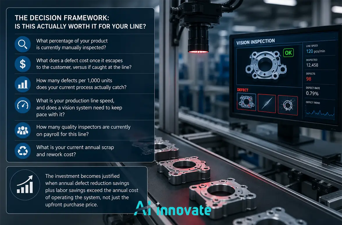
  •     What percentage of your product is currently manually inspected?
  •   What does a defect cost once it escapes to the customer, versus if caught at the line?
  •   How many defects per 1,000 units does your current process actually catch?
  •   What is your production line speed, and does a vision system need to keep pace with it?
  •   How many quality inspectors are currently on payroll for this line?
  •   What is your current annual scrap and rework cost?

The investment becomes justified when annual defect reduction savings plus labor savings exceed the annual cost of operating the system, not just the upfront purchase price.

The Decision Framework Is This Actually Worth It for Your Line

Where Most Vision Projects Actually Fail

The same failure patterns show up across deployment data repeatedly, and nearly all of them are avoidable with upfront planning rather than technology fixes after the fact.

  •   Underestimated integration complexity. The majority of manufacturers report integration costs running two to three times their initial estimate; budgeting real contingency for this upfront prevents the most common budget blowout.
  •   Inadequate training and change management. Many teams see a real productivity dip for several weeks post-deployment when training budget is treated as an afterthought rather than a planned cost.
  •   Poor data quality. A majority of deployments need to expand their training dataset within the first few months, usually because initial data collection did not capture the full range of shifts, lighting conditions, and product variation the line actually produces.
  •   Ignored model drift. AI models degrade in accuracy as production conditions shift over time, and most teams underestimate the ongoing cost of retraining, which should be budgeted as a recurring, not one-time, expense.
  •   Inconsistent lighting. A large share of vision inspection failures trace back to lighting design rather than software or algorithm limitations, making it one of the most underestimated line items in a vision system budget.

Where to Go Deeper

This guide covers the decisions that come before technology selection. Once you have a defined use case and budget, these resources go deeper on the specific choices ahead:

How AI-Innovate Fits Into Your Vision System Decision

Whichever path a manufacturer chooses, self-integration, a system integrator, or an existing hardware base, the detection accuracy that path actually delivers comes down to the intelligence layer running on top of the physical system, not just the camera and lighting hardware itself.

AIxEye: The Detection Layer That Adapts to Your Use Case

AIxEye provides real-time visual inspection tuned to the specific defect types, materials, and tolerances a line actually produces, whether that system was built in-house, installed by an integrator, or added onto existing camera hardware already on the floor.

AIxAm: 3D Surface and Geometry Inspection Where Dimensional Accuracy Matters

For the subset of use cases that fall under measurement and dimensional verification rather than surface inspection, AIxAm compares captured part geometry against CAD reference models, the capability a straightforward 2D defect detection setup was never built to provide.

AIxCore: Edge Processing That Keeps Detection Fast Enough to Matter

AIxCore handles on-site inference so inspection decisions happen at production speed rather than depending on a network round trip, a requirement that applies regardless of which budget tier or deployment path a manufacturer chooses.

Final Thoughts

The manufacturers who get real value from vision systems are not the ones who chase the most advanced technology first. They are the ones who define the actual use case before evaluating vendors, budget realistically using total cost of ownership rather than hardware price alone, and choose a build, buy, or integrate path that matches their internal technical capability and project scope.
Getting those decisions right before diving into camera specs, sensor types, and model architectures is what separates the 68 percent of manufacturers who overshoot their first vision system budget from the ones who deploy on plan and see positive ROI by year two. This guide is meant to get those foundational decisions right; the deeper technical guides linked above take you the rest of the way once they are.

Frequently Asked Questions

How much does a machine vision system cost for a manufacturing line?

Entry-level single-line systems start around $3,000 to $10,000, mid-range production-ready systems run $50,000 to $150,000, and high-end enterprise deployments range from $150,000 to $500,000 or more, depending on camera complexity, AI model sophistication, and integration scope.

It depends on internal technical capability and project complexity. Manufacturers with strong technical teams can self-integrate simple, single-line inspection tasks using off-the-shelf smart cameras and no-code platforms. Complex multi-camera lines, full automation cells, or projects requiring deep engineering expertise generally benefit from a system integrator.

A pilot deployment on a single line typically takes 2 to 3 months following a 1 to 2 month assessment phase, with turnkey integrator projects generally taking 8 to 16 weeks from design to production go-live. Enterprise-wide rollout across multiple lines extends the full timeline to 9 to 18 months depending on plant count.

Conservative economic viability generally starts around 500,000 units annually per line, with optimal returns above 1 million units annually. High-defect-cost industries like semiconductors can justify investment at volumes as low as 100,000 units annually due to the high cost of an individual escaped defect.

Integration complexity is consistently underestimated, often running two to three times initial estimates. Inadequate training budgets, poor initial data quality requiring dataset expansion, and underestimated ongoing model maintenance costs round out the most common sources of budget overrun.

A system integrator designs and installs the physical vision system, cameras, lighting, and mounting hardware. An AI inspection platform is the intelligence layer that runs on top of that hardware, often deployable on equipment a manufacturer already owns, and is what actually determines detection accuracy once the physical system is in place.

Ai-Innovate uses only high-quality sources, including peer-reviewed studies, to support the facts within our articles.

3D Machine Vision Inspection for Metal Parts

3D Machine Vision Inspection for Metal Parts

A bore machined 0.05mm undersize will not accept its mating shaft. A gasket groove cut 0.1mm too shallow will leak under pressure. A mounting hole drilled 0.5mm out of true position will prevent a fastener from ever seating correctly. None of these are surface defects. A metal part can look flawless, no scratches, no discoloration, no visible damage, and still fail completely because its actual geometry does not match what the engineering drawing specifies. That is a fundamentally different inspection problem than catching a scratch or a stain, and it is exactly the problem 3D machine vision was built to solve for metal parts.

This distinction matters more than it might seem. Surface defect detection asks whether a part looks correct, the focus of most metal defect detection use cases. Dimensional inspection asks whether a part measures correctly, whether its bores, flatness, weld profiles, and tolerances actually match the CAD model it was supposed to be manufactured from. For cast, forged, machined, and welded metal components, that second question is often the one with real consequences: a part that passes visual inspection can still be scrapped, returned, or cause an assembly failure months later if its geometry was never actually verified.

This guide covers the 3D vision technologies used for dimensional inspection of metal parts, how they compare to traditional coordinate measuring machines, what accuracy is actually achievable, and where this technology fits on a real production line.

Why Metal Parts Demand Dimensional Inspection, Not Just Surface Inspection

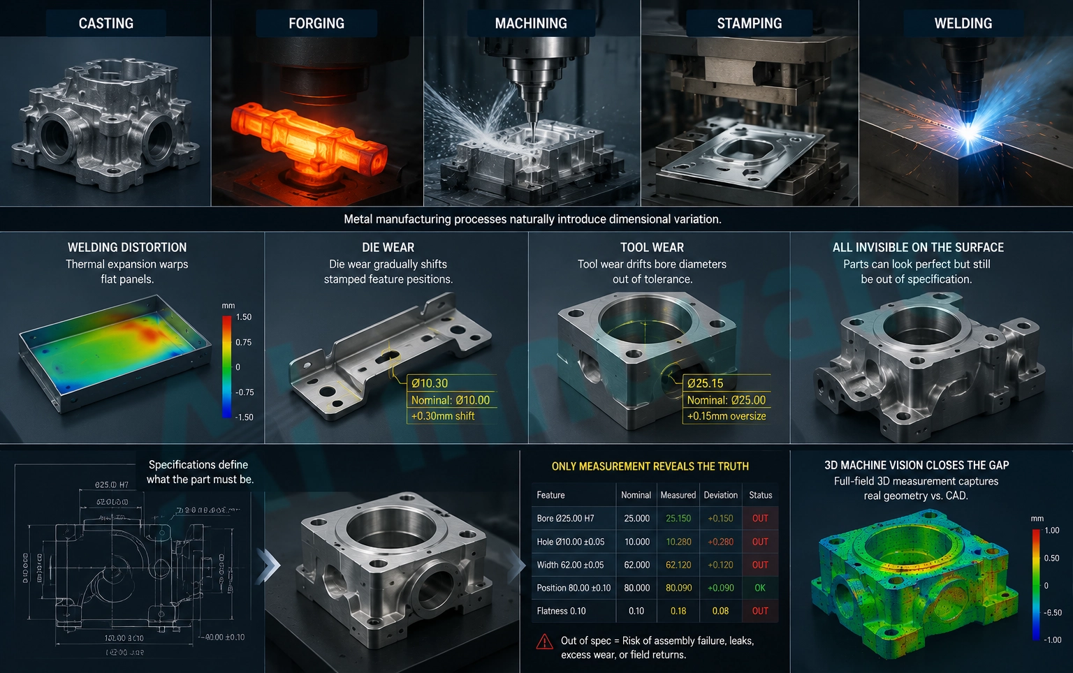
Metal manufacturing processes, casting, forging, machining, stamping, and welding, all introduce dimensional variation as a natural byproduct of the process itself. Thermal expansion during welding warps flat panels. Die wear gradually shifts stamped feature positions.

Tool wear on a CNC lathe slowly drifts bore diameters out of tolerance long before the tool visibly needs replacement. None of these failure modes are visible on the surface. They only show up when someone actually measures the part against its specification, which is precisely the gap 3D machine vision closes for metal components specifically.

Why Metal Parts Demand Dimensional Inspection, Not Just Surface Inspection

The 3D Vision Technologies Used for Metal Part Inspection

Several distinct optical technologies are used to capture the three-dimensional geometry of a metal part, each with real trade-offs for accuracy, speed, and suitability to different metal surface finishes, extending the broader 2D vision vs 3D vision systems for inspection comparison specifically into dimensional measurement on metal.

Structured Light Scanning

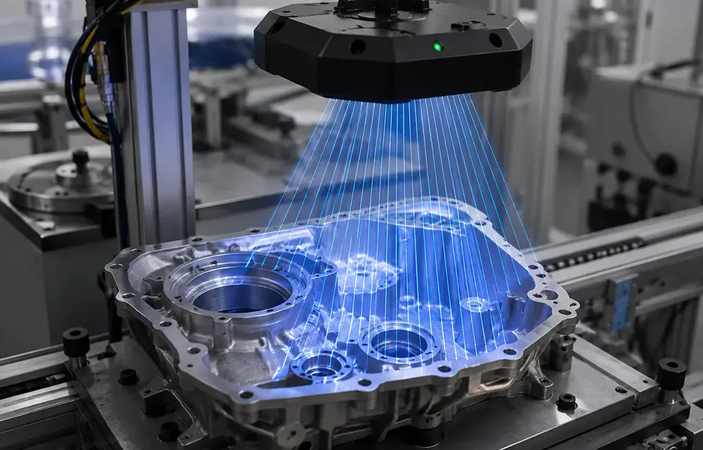
Structured light systems project a pattern, typically stripes or a grid of dots, onto the part surface and reconstruct its shape from how that pattern distorts across the geometry. This produces a dense point cloud well suited to complex freeform surfaces on cast and machined parts, and blue-light variants in particular deliver strong accuracy on parts up to roughly 500mm in size.

Laser Triangulation

A laser triangulation sensor projects a line onto the part and measures how that line’s position shifts as it crosses surface geometry, calculating a height map from the displacement. This technology handles reflective and dark metal surfaces better than most alternatives, making it a common choice for weld bead inspection, gap-and-flush measurement, and surface profiling at high speed on a moving line.

Photogrammetry

Photogrammetry determines part geometry by analyzing multiple images captured from different angles, reconstructing three-dimensional shape through triangulation across those views. It scales more effectively to larger parts than structured light or laser triangulation, though typically at a lower accuracy band, making it a common choice for large fabricated assemblies rather than small precision components.

Time-of-Flight Sensors

Time-of-flight cameras calculate depth by measuring how long light takes to reflect back from a surface, offering faster but lower-resolution 3D capture. This makes them well suited to robotic bin picking and large-object guidance, where millimeter-level accuracy is sufficient and speed matters more than micron-level precision.

Accuracy by Technology: What the Numbers Actually Show

Accuracy varies meaningfully by capture technology, part size, and surface characteristics, and understanding these bands matters when specifying a system for a real tolerance requirement.

Technology Typical Accuracy Best Suited For
Blue-light structured light 5-20 microns Parts up to ~500mm, complex freeform surfaces
Laser triangulation 10-50 microns Reflective or dark metal surfaces, weld profiling
Multi-view photogrammetry 20-100 microns Larger parts and assemblies
2D vision (telecentric lens) 10-50 microns (linear) Length, width, diameter on a single visible plane

The pattern worth noting: structured light and laser triangulation both deliver production-relevant accuracy at line speed, but neither matches a coordinate measuring machine on the tightest tolerance bands, a trade-off covered in more detail below.

GD&T Verification: How 3D Vision Actually Checks Tolerance

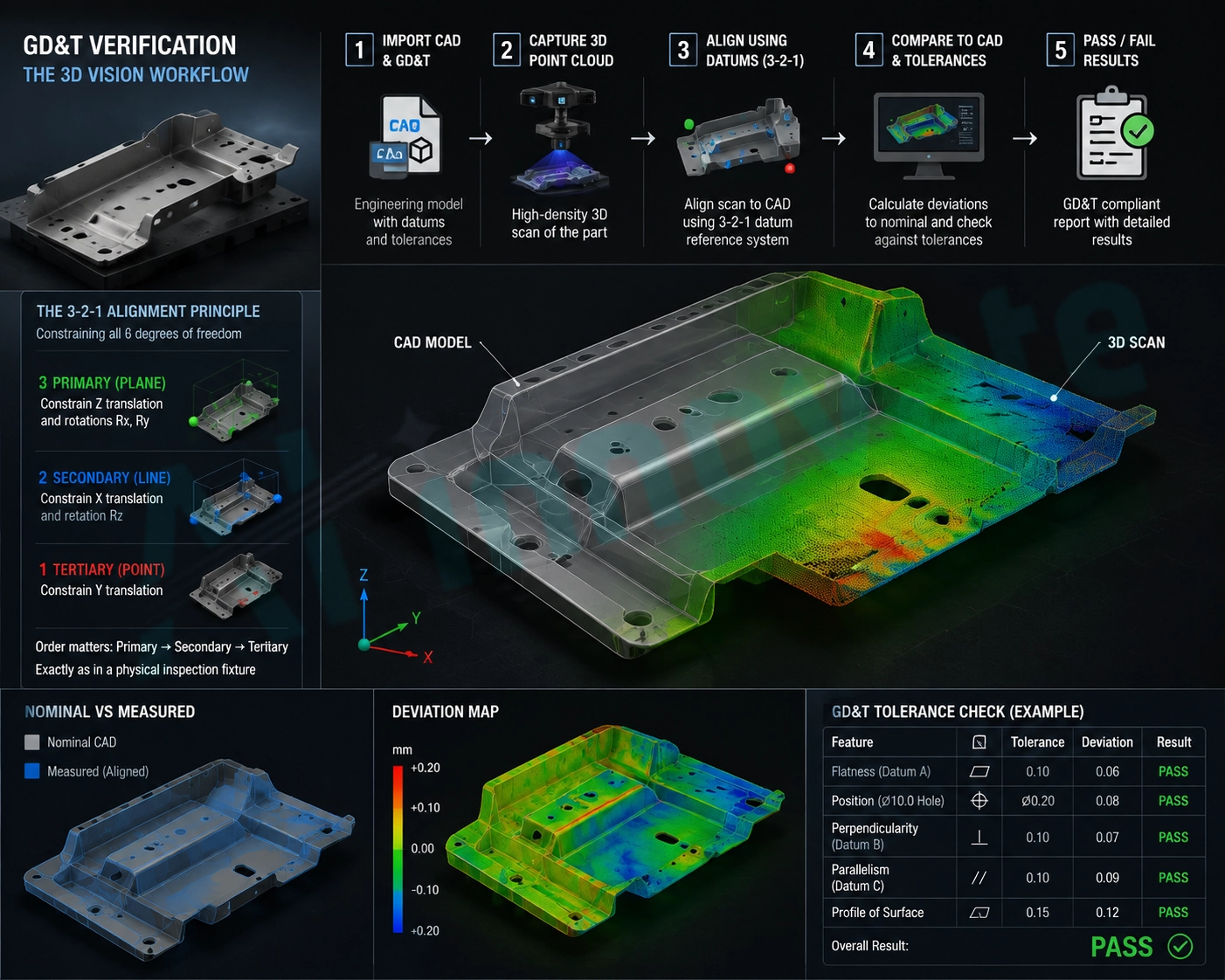
Geometric dimensioning and tolerancing, or GD&T, verification is where 3D vision moves from simply capturing shape to actually validating a part against engineering specification. The process imports the part’s CAD model along with its embedded datum features and their priority order, then aligns the captured scan to that model using a reference point system.

For sheet metal and machined parts, this commonly follows a 3-2-1 principle: three primary reference points, two secondary, and one tertiary, constraining all six degrees of freedom before any tolerance comparison happens. Only after this alignment, primary datum simulated first, then secondary, then tertiary, exactly as a physical inspection fixture would perform it, are deviations between the measured surface and the nominal CAD surface calculated and compared against the tolerances called out on the engineering drawing. This is what separates genuine GD&T verification from a simple visual pass or fail check.

3D Vision vs CMM for Metal Parts

Coordinate measuring machines remain the reference standard for dimensional metrology, and understanding where each technology genuinely fits avoids both over-investing in equipment a line does not need and under-specifying a system that cannot deliver the accuracy a part actually requires.

Factor CMM 3D Vision
Accuracy ±1-3 microns (lab), ±5-10 microns (shop floor) ±10-100 microns typical
Speed 30-60 minutes per part Milliseconds per cycle
Throughput Sample-based inspection 100% inline capable
3D Capability Full 3D including internal features Surface geometry only
GD&T Full compliance, ISO 10360 traceable Limited to surface-visible features
Contact Contact (may mark soft surfaces) Non-contact
Investment $100K-$500K+ $10K-$100K per station

In practice, the strongest quality strategies rarely choose one exclusively. A CMM validates the process during setup and first-article inspection, confirming what a genuinely correct part actually measures, while 3D vision then monitors every part in production, flagging drift before it produces an out-of-tolerance unit. The CMM defines “good.” The vision system makes sure every part continues to match it.

What Real Research Shows: Benchmarking 3D Scanners on Metal Parts

Independent, peer-reviewed research has directly tested this technology against metal parts rather than idealized lab samples. One study measured a purpose-built GD&T test part manufactured in 17-4PH stainless steel using selective laser melting, comparing five different optical measurement systems based on laser triangulation, conoscopic holography, and structured light against a coordinate measuring machine reference.

The researchers found that two portable systems, handheld laser triangulation and structured blue-light scanners, delivered the strongest combination of speed and dimensional accuracy for scanning additively manufactured metal parts, confirming that these technologies hold up on real metal surfaces and real GD&T requirements, not just idealized test targets.

Common Metal Part Applications for 3D Vision

The applications where 3D vision earns its value on metal parts are almost entirely dimensional and geometric, not cosmetic.

  •   Casting and forging verification against CAD, confirming a part’s actual shape matches its digital model within specified tolerance before it moves further down the line.
  •   Weld bead profile and volume measurement, verifying bead height, width, and volume meet specification on structural and pressure-critical welds.
  •   Warpage, flatness, and coplanarity checks, catching thermal distortion on stamped, welded, or heat-treated panels before assembly.
  •   Bore diameter, thread pitch, and gear tooth geometry verification, confirming precision machined features fall within the tolerance a mating part actually requires.
  •   Gap and flush measurement, verifying panel and component alignment in assemblies where fit and finish carry functional as well as cosmetic importance.

Where 3D Vision Fits Into a Metal Production Line

  1. Station placement. Position inspection immediately after the operation most likely to introduce dimensional variation, so drift is caught before additional value gets added to a non-conforming part.
  2. Part presentation. Use robots, conveyors, or indexing fixtures to present parts in a consistent, repeatable orientation, since inconsistent positioning introduces measurement variability unrelated to actual part quality.
  3. Reject handling. Automated diverters or reject bins remove non-conforming parts without stopping the line, maintaining throughput while segregating suspect material.
  4. Data integration. Connect inspection results to a manufacturing execution system for statistical process control and traceability, so a drifting process gets corrected during the shift that produced it rather than discovered later.
  5. Calibration and maintenance. Establish regular calibration intervals; lens cleaning and lighting verification keep measurement confidence stable over time, the same discipline that underlies computer vision in metal quality control broadly.

How AI-Innovate Powers 3D Vision Inspection for Metal Parts

Dimensional inspection for metal parts combines genuine technical difficulty, reflective surfaces, tight tolerances, and CAD-referenced comparison, with real production consequences when it is skipped or done inconsistently.

AIxEye: Real-Time Detection Across Surface and Dimensional Checks

AIxEye performs the visual inspection layer that catches surface-level issues alongside dimensional checks, giving a single inspection pass visibility into both how a metal part looks and how it measures, rather than requiring two entirely separate systems for what is often one production checkpoint.

AIxAm: Purpose-Built for 3D Surface and Geometry Inspection

AIxAm is built specifically for the 3D geometric and surface measurement challenges covered throughout this guide, comparing captured part geometry against CAD reference models to verify dimensional tolerance on castings, machined features, and weld profiles, the exact kind of GD&T-referenced verification that separates dimensional inspection from simple visual defect detection.

AIxCore: Edge Processing for Inline Measurement Speed

AIxCore handles the on-site inference that keeps 3D measurement fast enough to run inline at production speed, processing scan data locally so a dimensional deviation gets flagged and acted on immediately rather than after a delay that lets an out-of-tolerance part continue down the line.

Final Thoughts

3D machine vision inspection for metal parts solves a genuinely different problem than surface defect detection: verifying that a part’s actual geometry, its bores, flatness, weld profiles, and critical tolerances, matches what the engineering drawing specifies, catching the dimensional drift that visual inspection alone was never designed to see.

The manufacturers getting real value from this technology are not replacing their CMMs. They are using coordinate measuring machines to define what a correct part actually measures, then deploying 3D vision to verify that every part in production continues to match that standard, at a speed and volume no CMM could sustain on its own. For metal parts where a dimensional failure often surfaces only after assembly, or after a customer complaint, that shift from sampling to full inline dimensional verification is where the real return sits.

Frequently Asked Questions

What is the difference between 3D vision inspection and surface defect detection for metal parts?

Surface defect detection identifies visual flaws like scratches, discoloration, or contamination. 3D vision dimensional inspection measures a part’s actual geometry, bores, flatness, weld profiles, tolerances, against its CAD model, catching failures that are invisible on the surface but prevent a part from functioning correctly.

CMMs typically achieve 1 to 3 microns of accuracy in a lab environment, while 3D vision technologies generally deliver 10 to 100 microns depending on the specific method, part size, and surface characteristics. CMMs remain the reference standard for the tightest tolerances, while 3D vision trades some accuracy for dramatically faster, non-contact, 100% inline measurement.

Laser triangulation generally performs best on reflective or dark metal surfaces, while structured light scanning excels on complex freeform geometry like castings and machined parts. Peer-reviewed benchmarking on additively manufactured stainless steel parts found handheld laser triangulation and structured blue-light scanners delivered the strongest combined accuracy and speed for metal components specifically.

Generally no, particularly for internal features like bores and channels that require direct line of sight, and for the tightest GD&T tolerances. Most effective quality strategies use a CMM to validate the process during setup and first-article inspection, then deploy 3D vision to monitor every part during production.

GD&T, or geometric dimensioning and tolerancing, verification compares a scanned part’s geometry against its CAD model using a defined reference point system to align the two, then measures deviations against the specific tolerances called out on the engineering drawing, following the same datum-simulation principles a physical inspection fixture would use.

Casting, forging, welding, and precision machining benefit significantly, since each process introduces dimensional variation, thermal warpage, die wear, tool drift, weld distortion, that surface inspection alone cannot detect and that only shows up when a part’s actual geometry is measured against specification.

Ai-Innovate uses only high-quality sources, including peer-reviewed studies, to support the facts within our articles.

  1. AMD Machines. (2025). Dimensional Inspection: CMM vs Vision vs Laser Scanning. https://amdmachines.com/blog/dimensional-inspection-with-cmms-and-vision/
  2. iFactory AI. (2026). Dimensional Measurement and GD&T Verification with AI 3D Vision. https://ifactoryapp.com/ai-vision-camera/dimensional-measurement-gdt-verification-ai-3d-vision
  3. Ontiveros, S., Yagüe-Fabra, J. A., Jiménez, R., et al. (2018). Analysis of Modern Optical Inspection Systems for Parts Manufactured by Selective Laser Melting. Sensors, 18(6), 1876. https://www.ncbi.nlm.nih.gov/pmc/articles/PMC7308957/
Computer Vision in Fabric Inspection

Computer Vision in Fabric Inspection: AI-Powered Defect Detection

A defect in a roll of fabric can cut its market price by 45 to 64 percent. Traditional visual inspection, the industry’s default method for decades, catches only about 75 percent of defects even under ideal conditions, and that number falls further as inspector fatigue sets in over a shift. Fabric is one of the hardest materials computer vision has to inspect: it moves continuously, its texture varies naturally even when defect-free, and the same flaw can look completely different depending on fabric color, weave, and lighting angle.

This is not a theoretical problem. The textile industry generates close to 7 million tonnes of waste annually across the EU alone, a meaningful share of it tied directly to defects that went undetected until it was too late to prevent the loss. Computer vision has become the industry’s answer, but getting it right requires understanding a genuinely technical stack: camera technology, image processing, and detection algorithms, each with real trade-offs that determine whether a system actually catches what matters on a real production line.

This guide covers the camera technologies used in fabric inspection, the processing pipeline that turns raw images into defect decisions, how classical and deep learning approaches compare, and what a real industrial deployment actually looks like.

Why Fabric Is a Uniquely Hard Computer Vision Target

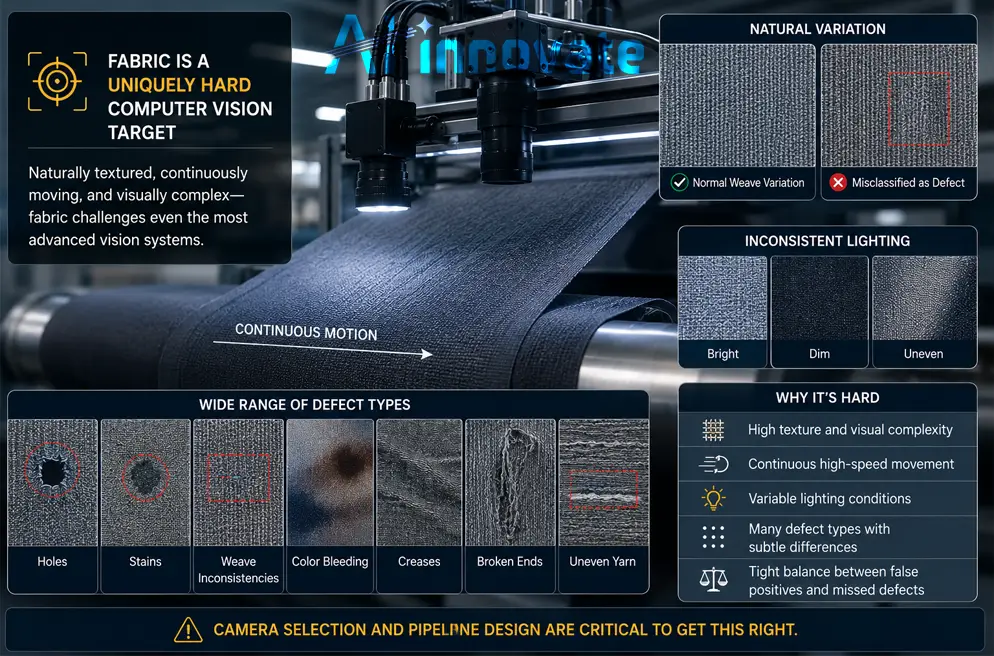
Unlike a flat metal panel or a rigid manufactured part, fabric is a continuously moving, naturally textured material with meaningful color and weave variation even within a single defect-free roll. A system tuned too tightly to one fabric’s texture will flag normal variation as a defect.

A system tuned too loosely will miss the real thing. Add continuous motion, inconsistent factory lighting, and the sheer variety of defect types, holes, stains, weave inconsistencies, color bleeding, creases, and the inspection challenge compounds quickly. This is exactly why camera selection and processing pipeline design matter so much more in fabric inspection than in many other industrial vision applications.

Why Fabric Is a Uniquely Hard Computer Vision Target

Choosing the Right Camera Technology

Different camera technologies are suited to different defect types, and the choice shapes everything downstream in the machine vision for defect detection pipeline.

Area-Scan Cameras

Area-scan cameras capture two-dimensional images similar to a standard photographic camera, making them effective and low-cost for static or slow-moving inspection, identifying stains, lines, pattern inconsistencies, and loose threads. Their limitation is field of view and throughput, which makes them less suited to high-speed continuous production.

Line-Scan Cameras

Line-scan cameras capture one line of pixels at a time, making them particularly suited to surfaces in continuous motion. They offer high spatial resolution and are ideal for fast-moving fabric rolls, detecting broken threads, transverse lines, and fine stains, though they require precise synchronization with fabric movement and consistent, uniform lighting to avoid distortion or missed defects.

Multispectral Cameras

Multispectral cameras capture images across multiple light bands, including infrared and ultraviolet alongside standard RGB, revealing chemical stains and yarn inconsistencies that evade RGB-only methods. This makes them valuable for defects invisible to the human eye, though at the cost of higher computational overhead and stricter lighting control requirements.

RGB-D (Depth) Cameras

RGB-D cameras capture standard color images alongside depth maps, enabling detection of three-dimensional defects like wrinkles, folds, and creases. Depth data helps distinguish real defects from shadows, a genuine advantage, though precision generally runs lower than dedicated industrial imaging systems, and performance declines on reflective or very smooth surfaces like silk or satin.

Thermal Cameras

Thermal cameras detect heat emissions, making them suited to identifying defects invisible to standard imaging, such as yarn density variation. Their sensitivity to ambient temperature changes means they require controlled environmental conditions to avoid false positives from thermal noise.

From Pixels to Decisions: The Core Processing Pipeline

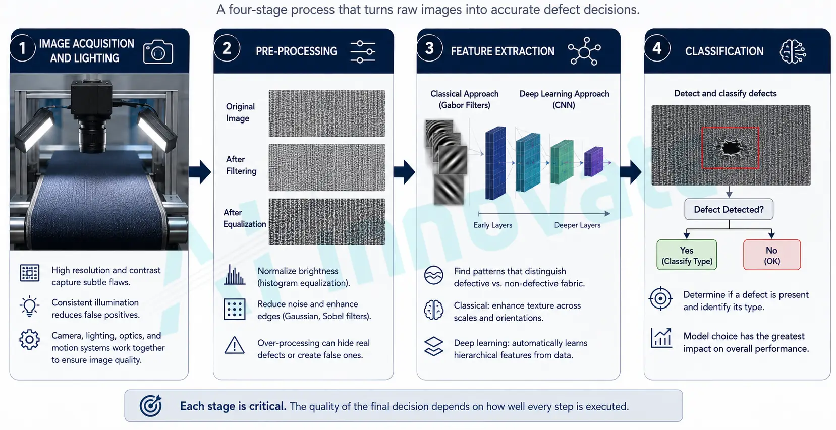
Regardless of camera choice, automated fabric inspection systems follow a consistent four-stage pipeline, each stage shaping how reliably the final defect decision holds up.

Image Acquisition and Lighting

The acquisition stage requires high image resolution, contrast, and consistent illumination to catch even subtle flaws. Beyond the camera itself, lighting, optics, and mechanical motion systems all factor into image quality, and poor lighting is one of the most common sources of false positives in real deployments, since shadows and inconsistent texture appearance can easily be mistaken for defects.

Pre-Processing

Pre-processing improves image quality and consistency before analysis, using techniques like histogram equalization to normalize brightness and Gaussian or Sobel filtering to reduce noise and highlight edges, the same fundamentals behind surface defect detection across other materials. 

This step has to be calibrated carefully: applied in excess, it can obscure genuine defects or introduce false ones, and grayscale conversion in particular can strip the color information needed to detect chromatic defects like discoloration.

Feature Extraction

Feature extraction identifies the patterns that distinguish defective from non-defective fabric. Classical approaches like Gabor filters enhance texture patterns across scales and orientations, while modern deep learning models learn optimal filters directly from labeled data, with early network layers detecting basic edges and textures and deeper layers combining them into abstract representations of structural anomalies.

Classification

The final stage determines whether a defect is present and identifies its type. This is where the choice between classical machine learning and deep learning object detection has the largest practical impact on system performance, covered in detail below.

From Pixels to Decisions The Core Processing Pipeline

Classical vs. Deep Learning for Fabric Inspection

Traditional machine learning can work well in controlled inspection environments, but deep learning is better suited to the variation and speed of modern textile production.

Parameter Classical Machine Learning Deep Learning
Feature Extraction Hand-engineered features Features learned automatically
Typical Models SVM, KNN YOLO, Faster R-CNN
Fabric Variation More sensitive to texture and lighting changes Better at handling complex visual variation
Defect Detection Works well with predefined patterns Learns complex defect characteristics
Accuracy KNN example: 95.48% YOLOv8: 0.756 mAP
Processing Speed Depends heavily on feature processing YOLOv5: 118 FPS
YOLOv8: 103.5 FPS
Scalability More difficult to adapt to new defect types Easier to retrain for new defects
Production Use Best for controlled applications Better suited to real-time automated inspection

The Practical Difference

  • Classical methods: Effective when defects are predictable and the inspection environment is highly controlled.
  • Deep learning: Better suited to production lines where fabric texture, defect appearance, lighting, and operating conditions can vary.

For modern automated fabric inspection, the key advantage of deep learning is not simply higher accuracy. It is the ability to learn complex visual patterns while maintaining the speed required for real-time inspection.

A Real-World Fabric Inspection Deployment

Computer vision has also been tested under actual textile production conditions, not just in laboratory experiments. In one Portuguese textile manufacturing line, researchers deployed YOLOv11n on an NVIDIA Jetson Orin Nano with two Intel RealSense RGB-D cameras positioned about one meter from the fabric.

The system inspected cotton and linen fabric moving at 15 meters per minute, looking for holes, color bleeding, and creases. It processed the camera feeds at approximately 100 frames per second and achieved a mean Average Precision (mAP) above 82%, demonstrating that edge-based AI can support real-time inspection at production speed

What the Results Reveal

The system didn’t perform equally well on every defect. Hole detection reached 87% precision, while color bleeding reached 62% precision.

The difference came largely from the imaging technology. RGB-D cameras are particularly effective at capturing depth and physical surface changes, which gives the system an advantage when detecting structural defects such as holes and creases. Color bleeding, however, depends more heavily on accurate color information.

This example highlights an important principle in automated fabric inspection: the camera and the AI model need to be selected together. Even a highly capable detection model cannot reliably identify a defect if the imaging system doesn’t capture the visual characteristics that distinguish it.

Best Practices for Deploying Computer Vision on a Fabric Line

  1.  Match camera technology to your primary defect types. A system built around RGB-D sensors will underperform on chromatic defects like color bleeding regardless of how well the detection model is trained.
  2. Invest in consistent, controlled lighting before optimizing the model. Published deployments consistently identify poor lighting as the leading cause of false positives, more so than model architecture choice.
  3. Avoid preprocessing that strips information your defects depend on. Grayscale conversion, for instance, improves contrast for structural defects but destroys the color data chromatic defect detection needs.
  4. Choose deep learning object detection over classical classifiers for production deployment. Classical methods can match or exceed deep learning accuracy in narrow, controlled tests, but they scale poorly to the variability of a real factory floor.
  5. Deploy at the edge for real-time response. Cloud-based processing introduces latency and connectivity risk that time-sensitive real-time defect analysis, where even minor delays mean undetected defects, generally cannot tolerate.

How AI-Innovate Powers Computer Vision Fabric Inspection

Fabric inspection is a genuinely difficult computer vision problem: continuous motion, natural texture variation, and defect types that span structural, chromatic, and depth-based categories all at once. Solving it well requires more than a single camera and a generic model.

AIxEye: Detection Tuned to Fabric-Specific Defects

AIxEye performs the real-time visual inspection at the core of fabric quality control, trained to recognize the specific defect signatures, holes, color bleeding, creases, weave inconsistencies, that matter on a given production line, rather than relying on a single generic detection profile that treats every material the same way.Lorem ipsum dolor sit amet, consectetur adipiscing elit. Ut elit tellus, luctus nec ullamcorper mattis, pulvinar dapibus leo.

AIxAm: Closing the Data Gap for Rare Defects

AIxAm addresses a challenge fabric inspection shares with nearly every industrial vision application: some defect types occur too rarely in normal production to build a large real-world training set. Generating synthetic training examples for these rarer cases closes that gap without waiting months to accumulate enough real-world defect images.

AIxCore: Real-Time Processing at Production Speed

AIxCore handles the on-site inference that keeps inspection running at the pace fabric actually moves through production, without the latency a cloud round-trip would introduce on a continuously moving material where every second of delay is more fabric that has already passed the inspection point.

Final Thoughts

Computer vision in fabric inspection is a genuinely technical discipline, camera technology, image processing, and detection algorithm choice all shape what a system can reliably catch, and getting any one of them wrong quietly limits the whole pipeline regardless of how good the rest of the system is.

The deployments delivering real results are not the ones chasing the single most advanced model available. They are the ones that start by understanding which defect types matter most on their specific line, choose camera technology that can actually see those defects, and build the processing pipeline around that choice rather than forcing one generic setup to handle everything. In an industry where a single undetected defect can cut a fabric’s value by half, that kind of deliberate, defect-specific engineering is where the real return sits.

Frequently Asked Questions

What type of camera is best for fabric defect detection?

There is no single best camera; the right choice depends on the defect types that matter most. Line-scan cameras suit high-speed continuous fabric, RGB-D cameras excel at structural defects like creases and holes, and multispectral cameras are needed for chemical or color-based anomalies that RGB imaging alone cannot detect.

Manual visual inspection typically catches around 75 percent of defects and declines further with inspector fatigue. Published deep learning systems have reported mean Average Precision figures above 82 percent in real industrial deployments, with individual defect types like holes reaching accuracy above 87 percent.

Detection reliability depends heavily on whether the chosen camera technology is suited to that defect type. A system built around depth-sensing cameras, for example, typically performs better on structural defects like holes and creases than on color-based defects like bleeding, which depend on chromatic information the camera may not capture as strongly.

Most published research and real deployments focus on solid-colored, patternless fabric, since pattern and texture introduce additional visual complexity that current models generalize to less reliably. Extending detection to patterned fabrics remains an active area of development.

Real-time fabric inspection is generally better suited to local edge processing rather than cloud computing, since even minor latency can mean a defect passes the inspection point undetected. Published deployments using edge devices have achieved real-time processing at production speeds without cloud dependency.

Camera and lighting choice consistently outweigh model architecture as the limiting factor. A well-optimized detection model still cannot reliably catch a defect type the camera technology was never suited to seeing in the first place, which is why camera selection should come before model selection in any deployment plan.

Ai-Innovate uses only high-quality sources, including peer-reviewed studies, to support the facts within our articles.

2D Vision vs 3D Vision Systems for Inspection

2D vs 3D Machine Vision: Which Inspection System Is Better?

Picking the wrong vision system does not fail quietly. It fails on the line, in the form of missed defects a 2D camera was never built to see, or in wasted budget on 3D hardware a simple label-check never needed. Machine vision has become the default way manufacturers catch defects, verify assembly, and guide robots, but the technology splits into two fundamentally different approaches, and choosing between them is not a matter of picking the “better” one. It is a matter of matching the system to what your inspection actually needs to measure.

That distinction trips up more manufacturing teams than it should. A 2D system that excels at reading a barcode will never catch a warped panel, no matter how good its camera is, because it was never designed to see depth in the first place. A 3D system brought in to catch a printed label defect is often solving a problem a much cheaper 2D setup could have handled just as well. Getting this choice right affects your budget, your inspection speed, and ultimately how many real defects make it past your line.

This guide breaks down what 2D and 3D vision systems actually are, where each one genuinely excels, how they compare side by side, and how manufacturers across industries decide which one, or both, belongs on their production line.

What Is a 2D Vision System?

A 2D vision system captures and analyzes flat images across two axes, width and height, using standard area scan or line scan cameras paired with controlled lighting. It evaluates contrast, color, edges, and pattern to identify surface-level features and defects. Because it processes a comparatively small amount of data per image, a 2D system captures and analyzes frames quickly, which is exactly why it remains the standard choice for high-speed inspection lines.
What 2D vision cannot do is see depth. It has no way to measure height, volume, or the third dimension of an object’s shape, which means it is fundamentally blind to defects that only show up as a change in surface elevation rather than a change in surface appearance. It is also more sensitive to lighting conditions than 3D systems, since shadows and reflections can distort a flat image in ways that a depth-based system simply is not affected by.

What Is a 2D Vision System

What Is a 3D Vision System?

A 3D vision system adds a third axis, depth, to the inspection, using technologies like structured light, laser triangulation, stereo vision, or time-of-flight sensors to build a volumetric model of the object being inspected. Rather than producing a flat image, it outputs a point cloud or height map that captures the object’s actual shape and dimensions in space.
This depth capability is what makes 3D vision essential for tasks a 2D camera cannot perform at all: measuring weld bead height, verifying that a component sits flush within a tolerance of a fraction of a millimeter, checking fill level in a sealed container, or guiding a robot to pick a part out of a bin where every item sits at a different height and angle. The tradeoff is real. 3D systems process significantly more data per capture, require more careful calibration and vibration control, and typically carry a meaningfully higher upfront cost than an equivalent 2D setup.

3D Vision System

How 2D and 3D Vision Systems Actually Compare

Factor 2D Vision 3D Vision
Dimensions Captured Width and height (X, Y) Width, height, and depth (X, Y, Z)
Typical Sensors Area scan or line scan cameras Structured light, laser triangulation, stereo vision, time-of-flight sensors
Data Output Flat pixel-based image Point cloud or height map
Processing Speed Fast, lower data volume Slower, higher data volume
Lighting Sensitivity High; shadows and reflections can distort results Lower; less dependent on controlled lighting
Typical Cost Lower, often 50–70% less than comparable 3D systems Higher upfront investment
Best Suited For Labels, barcodes, presence checks, OCR, flat surface defects Height measurement, volume analysis, warping detection, complex geometry inspection, robotic guidance

The table captures the core tradeoff well: 2D wins on speed and cost for anything that can be judged from a flat image, while 3D wins wherever depth, shape, or spatial position is the actual thing being measured.

When to Use a 2D Vision System

  • Reading labels, barcodes, or printed text. OCR and code verification depend on contrast and pattern recognition, exactly what 2D vision is built for.
  • Inspecting flat surfaces at high speed. Scratches, discoloration, and print quality on a fast-moving line are well within 2D’s core strength.
  • Verifying presence or absence of a component. Confirming a screw, label, or part is in the correct location does not require depth data.
  • Working in a well-controlled, well-lit environment. 2D performs best when lighting and camera position stay consistent.

When to Use a 3D Vision System

  • Measuring height, volume, or flatness. Weld bead thickness, fill level, and coplanarity checks all require true Z-axis data.
  • Inspecting complex or irregular geometry. Molded and machined parts with tight tolerances need a full spatial model to verify against specification.
  • Guiding robots in unstructured environments. Bin picking, where parts sit at random heights and orientations, is a task 2D vision cannot do at all.
  • Working with reflective or variable-lighting conditions. 3D systems are generally more robust to the shadows and glare that disrupt 2D imaging.

2D and 3D Vision in Action Across Industries

Different industries rely on 2D and 3D vision systems differently, depending on the inspection task at hand. 2D vision is ideal for fast, surface-level inspections, while 3D vision is essential for applications requiring accurate depth and dimensional measurements.

Automotive Manufacturing

Modern vehicles involve more than 30,000 individual parts, so manual inspection is impractical at production speed.

  • 2D Vision: Confirms that the correct parts are present at each stage of assembly.
  • 3D Vision: Verifies weld quality, panel gap tolerances, and other depth-dependent measurements.

Electronics Manufacturing

The production of electronics relies on these two technologies to inspect increasingly complex assemblies.

  • 2D Vision: It confirms component placement and reads text on printed circuit boards (PCBs).
  • 3D Vision: It measures solder paste height and connector coplanarity, defects that are functionally invisible to a flat image.

Pharmaceutical and Food Packaging

Depending on the task, packaging lines use different vision technologies.

  • 2D Vision: Handles label compliance and print verification.
  • 3D Vision: Measures blister pack seal integrity and container fill levels.

Many of these inspections are related to surface defect detection. In this process, manufacturers identify scratches, dents, seal defects, contamination, and other imperfections on packaged goods before they leave the production line.

Choosing Between 2D and 3D for Your Inspection Line

The right choice depends on more than just camera technology. Consider the following factors when selecting a 2D or 3D vision system for your inspection line:

  1.   Identify what you are actually measuring. If the defect or check is visible in a flat image, a 2D system likely handles it. If it requires height, volume, or shape data, only 3D will work.
  2.   Assess your production speed. High-throughput lines with simple checks favor 2D’s faster capture and processing. Moderate-speed or stop-and-inspect stations can absorb the additional processing time 3D requires.
  3.   Evaluate your lighting environment. Inconsistent or difficult lighting conditions push the decision toward 3D, which is inherently less sensitive to shadows and reflections.
  4.   Factor in total cost, not just hardware price. A 2D system costs less upfront, but if it cannot catch the defects that matter most, the downstream cost of missed defects and rework can outweigh the initial savings.
  5. 5. Consider a hybrid setup. Many production lines run both, using machine vision for defect detection at multiple stages, 2D for fast surface-level screening and 3D for the depth-dependent checks that follow.

Why Many Production Lines Use Both

The most common real-world setup is not “2D or 3D” but “2D and 3D,” each covering the inspection tasks the other cannot. A 2D camera might confirm a label is present and correctly printed, while a 3D sensor downstream verifies that the same container is filled to the correct height, a distinction our earlier look at machine vision systems for automated inspection covers in more depth.

The same layered logic applies to component-level checks: just as object detection for industrial machine vision identifies and classifies parts within a 2D image, 3D systems take over the moment a task requires confirming that a part’s physical geometry, not just its visual appearance, meets specification. This layered approach mirrors the same principle behind aircraft surface and component inspection: no single vision technology covers every defect type, and the strongest inspection programs combine methods rather than forcing one system to do a job it was never designed for.

Bringing the Right Vision System to Your Production Line

Choosing between 2D and 3D vision isn’t about selecting the most advanced technology, it’s about selecting the right tool for the inspection task. Successful machine vision projects begin by identifying exactly what needs to be measured, whether that’s a surface defect, a dimensional variation, or a combination of both. Matching the inspection objective to the appropriate vision technology helps manufacturers improve detection accuracy while avoiding unnecessary hardware costs.

At AI-innovate, we’ve developed our vision inspection solutions with this flexibility in mind. Rather than treating 2D and 3D vision as competing technologies, we design systems that use the most suitable data for each application.

  • AIxEye performs AI-powered defect detection on both surface appearance and dimensional inspection tasks, allowing manufacturers to inspect products using either 2D images, 3D data, or a combination of both.
  • AIxCam streamlines the collection and annotation of training data, helping manufacturers build reliable AI models for new defect types across both image-based and depth-based inspections.
  • AIxCore delivers real-time edge AI processing, enabling both high-speed 2D inspections and data-intensive 3D analysis without introducing delays to the production line.

Final Thoughts

2D vision systems win on speed, simplicity, and cost for any inspection task that can be judged from a flat image, while 3D vision systems are the only option once height, volume, or complex geometry becomes part of what needs to be measured.

In practice, the manufacturers who get the most value from machine vision are rarely the ones who pick a single technology and standardize on it everywhere. They are the ones who map each inspection task to the system actually built for it, often running 2D and 3D side by side on the same line, and treat the decision as an ongoing fit exercise rather than a one-time hardware purchase.

Confused About Where to Start with AI?

Our specialists help you identify the right AI approach based on your process, data, and goals.

Frequently Asked Questions

What is the main difference between 2D and 3D vision systems?

The main difference is depth. 2D vision systems capture flat images across width and height only, while 3D vision systems add a third axis to measure depth, volume, and complex geometry that a flat image cannot represent.

Not necessarily. 3D vision is more accurate for anything involving depth, height, or shape, but 2D vision is equally or more accurate for surface-level tasks like label reading, barcode scanning, and contrast-based defect detection, since it is purpose-built for exactly that.

3D vision systems typically cost significantly more upfront than 2D systems, with industry estimates placing 2D systems at roughly 50 to 70 percent lower cost. The gap narrows when factoring in the cost of defects a 2D system would miss entirely.

Yes, and this is increasingly the standard approach. Many manufacturers use 2D vision for fast surface-level checks like label verification and 3D vision for depth-dependent measurements like weld height or fill level, combining both on a single line to cover the full range of defect types.

Automotive, aerospace, and electronics manufacturing rely heavily on 3D vision for tasks like weld profiling, gap measurement, and solder height verification, where tolerances are tight enough that depth data is not optional.

3D vision is generally more robust to lighting variation and shadows than 2D vision, but it is not immune to every environmental challenge, particularly with highly reflective or perfectly uniform surfaces, which can still require specific calibration or technique adjustments.

Ai-Innovate uses only high-quality sources, including peer-reviewed studies, to support the facts within our articles.

  1. KEYENCE Corporation. Key Differences Between 2D and 3D Vision Systems. https://www.keyence.com/products/vision/resources/vision-resources/key-differences-between-2d-and-3d-vision-systems.jsp
  2. Averroes. (2026). 2D Vision vs 3D Vision Systems for Inspection. https://averroes.ai/blog/2d-vision-vs-3d-vison-systems
  3. Photoneo. (2025). 2D vs 3D Vision System: Finding a Perfect Fit For Your Application. https://www.photoneo.com/2d-vs-3d-vision-system/
Machine Vision vs AI Vision for Quality Control

Machine Vision vs AI Vision for Quality Control: Which One Actually Works?

A single missed defect can cost a manufacturer a recall, a contract, or a compliance flag. Most production teams understand the risk, yet many facilities are still running inspection systems that can’t keep pace with changing products or unfamiliar defect types. AI vision inspection solves this by using deep learning models that learn from real production data instead of pre-written rules. For operations managing product variety, irregular defects, or multiple lines, the difference between machine vision vs AI vision quality control shows up directly in catch rates, changeover time, and long-term maintenance cost.

Here’s how the two systems compare, where the performance gaps appear, and what the data actually shows.

How Traditional Machine Vision Systems Work

Traditional machine vision relies on cameras, fixed lighting, and rule-based software to inspect parts at line speed. Engineers program the system to look for specific characteristics: pixel thresholds, edge profiles, dimensional tolerances, contrast values. Each inspection result is the outcome of a rule a person wrote before production started.

Machine vision for defect detection using this approach works reliably when defect types are stable and can be fully defined before the system goes into production.

What Rule-Based Inspection Does Well

Rule-based systems perform reliably in narrow, stable conditions. Single-product lines with consistent lighting, known defect types, and no planned product changes are where these systems earn their place. The logic is deterministic, transparent, and auditable, which matters in regulated manufacturing environments where every inspection decision needs to be traceable.

Where Traditional Machine Vision Limitations Appear

Performance degrades quickly when conditions shift:

  • A new product variant enters the line
  • Lighting changes as fixtures age
  • A supplier switches material grades
  • An unfamiliar defect type starts appearing in production

Every change requires an engineer to rewrite inspection rules from scratch, and each rewrite affects every inspection point on the line separately. For high-mix manufacturers, those engineering costs compound with every additional SKU and every product revision. Traditional machine vision limitations aren’t a design flaw. They’re structural: the system can only flag what someone already anticipated, which is a real constraint when production complexity keeps growing.

How Traditional Machine Vision Systems Work

How AI Vision Inspection Works

AI-based inspection replaces hand-coded rules with deep learning models trained on labeled image data. A convolutional neural network (CNN) reviews thousands of examples of acceptable and defective parts, learning the visual patterns associated with each outcome [2]. Deep learning models generalize from those examples rather than matching fixed rules, which is what separates them architecturally from traditional algorithmic approaches [3]. At inspection time, the model compares incoming parts against what it learned rather than against fixed thresholds.

Automated visual inspection built on this architecture generalizes across part variation without requiring engineers to define every possible failure mode before the system goes live.

The Core Difference Between Deep Learning and Classical Vision Systems

Deep learning vs classical vision systems comes down to how inspection decisions get made:

  • Rule-based: Does this part match the programmed specification?
  • AI-based: Does this part show visual patterns associated with defects?

The second approach handles irregular, subtle, or variable defects far more effectively. Surface porosity in castings, inconsistent coatings on textiles, micro-cracks in stamped metal: none of these have the consistent geometry that pixel-level thresholds require. Trained models detect them through pattern recognition built from real production examples, not pre-defined coordinate logic.

AIxEye is built for this replacement scenario, running real-time adaptive inspection that responds to actual production variation rather than requiring logic rewrites each time conditions shift. Operations relying on real-time defect analysis benefit most from this architecture, particularly where product mix is high or defect types change between runs.

How AI Models Improve With Production Feedback

When operators flag a false rejection or a missed defect, that image enters the retraining pipeline and the next model version is more accurate. Rule-based systems don’t work this way. A rule that misses a defect keeps missing it until someone manually rewrites the logic and revalidates the change.

AOI vs AI Inspection Systems: Side-by-Side Comparison

Automated optical inspection (AOI) is the most common form of rule-based machine vision in electronics manufacturing [4] and the baseline most AI inspection systems get evaluated against. The table below shows where rule-based vision vs AI inspection diverges across the capabilities that matter most in production.

Capability AOI / Rule-Based AI Inspection
New product setup Full reprogramming required Retrain using new labeled images
Handles lighting or surface variation Poorly Well
Learns from production errors No Yes
Detects irregular or complex defects Limited to predefined defect types Generalizes from training data
False rejection rate under variation Higher Lower with trained models
Engineering cost per new SKU High Lower after initial deployment
Long-term maintenance burden High Decreases as the model matures

Many facilities run both approaches simultaneously: AOI on high-volume stable lines and AI inspection where product mix or defect variability is greater. The decision comes down to which environment each specific line represents.

Where AI Vision Outperforms Rule-Based Inspection Systems

There are numerous areas in which AI takes the lead from older methods of inspection.

Accuracy on Complex Defect Types in Manufacturing

A 2022 peer-reviewed study in the International Journal of Precision Engineering and Manufacturing-Green Technology tested rule-based and deep learning inspection across multiple surface defect categories. CNN-based models reached 98.3 percent detection accuracy compared to 84.1 percent for traditional methods on complex defect types . The accuracy gap holds across most defect detection in manufacturing environments where surface conditions, lighting, or part geometry vary between production runs. On simple, stable defect categories the gap narrows, but AI systems maintain an ongoing advantage as production data feeds back into retraining cycles.

How AI Inspection Reduces Changeover Time vs Rule-Based Systems

When a new product enters the line, an AI system needs labeled images and a retraining cycle, which typically runs in days. Reprogramming a rule-based system takes weeks, and that’s before formal revalidation begins. For manufacturers managing 20 or more active SKUs, this gap compounds across every product transition.

Regulated industries face additional pressure here. Inspection logic changes require formal revalidation, and a rule-based system updating threshold values across dozens of parameters goes through that process every time. An AI system that retrains without modifying its core architecture can often move through revalidation faster. Explainable AI in quality inspection frameworks address this directly, giving regulated manufacturers the audit trail they need without the per-parameter revalidation burden rule-based systems carry.

Scaling AI Inspection Across Production Lines and Facilities

AI models train once and deploy everywhere. Updates push to all inspection points simultaneously without per-camera engineering work. As manufacturers expand automation across multiple facilities , the difference between centralized AI model management and individually maintained rule sets becomes a direct operational cost. A manufacturer running five plants on the same product line would need five independent rule-based setups, each maintained separately. A centrally managed AI model deploys once and holds consistent behavior across all five sites, with a direct impact on staffing, downtime, and total operating cost over a multi-year horizon.

System Architecture: Edge Deployment vs Fixed Hardware Logic

Traditional machine vision runs fixed algorithms on dedicated hardware at each camera. Updating inspection logic on a 10-camera line means 10 separate engineering interventions, each requiring validation before returning to production use. If a defect type starts slipping through, every camera on the line needs individual attention before the fix takes effect.

AIxCore changes this architecture at the hardware level. It’s an industrial AI edge computer powered by NVIDIA Jetson Orin AGX, running trained models on-site so inference happens directly on the production line. 

Machine learning in quality control deployed through a centralized edge architecture scales by pushing updates rather than by multiplying engineering effort, which makes a measurable difference as line count and SKU complexity grow.

The Dataset Advantage AI Inspection Systems Build Over Time

Rule-based systems process images and discard them. There’s no historical archive, no defect record, and no data pipeline feeding back into future detection performance.

AI inspection systems accumulate institutional knowledge with every cycle. AIxCam integrates imaging hardware with the training pipeline, capturing and storing production images in formats that feed directly into model retraining. Over a production run, the system builds a dataset reflecting actual defect patterns on your specific parts, materials, and line conditions.

The accumulated dataset delivers ongoing value across several areas:

  • Retraining when defect patterns shift with new materials or process changes
  • Full image-level traceability for quality audits and compliance reviews
  • Faster onboarding for engineers who need documented defect history
  • Cross-generation benchmarking of detection performance over time

Every cycle of a rule-based system produces nothing that improves future detection. Each cycle of an AI inspection system adds to the model’s long-term accuracy.

When Rule-Based Machine Vision Still Makes Sense

AI inspection isn’t the right fit for every operation. There are genuine cases where rule-based systems remain the practical choice.

Stick with rule-based machine vision when:

  • Your line runs one or two product variants with no planned changes
  • Defect criteria are fully specified, stable, and regulatory-defined
  • Lighting and surface conditions are tightly controlled and consistent
  • Hard regulatory requirements demand deterministic, fully auditable inspection logic

Move toward AI-driven quality control when:

  • You’re managing high product mix with frequent changeovers
  • Defects are complex, variable, or not fully characterized in advance
  • You need the inspection system to improve with production feedback
  • You’re scaling inspection across multiple lines or facilities

In 2026, the majority of manufacturers operating on a mixed production schedule will align with the second profile. The product variety has increased, the cycle times have decreased, and customer quality standards have risen. In such cases, rule-based logic may reach its limits. Manufacturers transitioning to AI-driven quality control are also realizing that these capabilities seamlessly extend to AI for quality assurance at the process level, not just the inspection point.

How AI-innovate Supports AI Visual Inspection Implementation

We help manufacturers build AI visual inspection systems around their actual line conditions, parts, and defect history, not a pre-packaged solution dropped onto the floor. The dataset, the hardware configuration, and the model tuning are where these projects succeed or fail, and that’s where we focus.

The components we use:

  • AIxCam provides simulation tools and synthetic data generation for rare defect modes that don’t occur often enough on the live line to train a reliable model from production data alone, making it the most important tool for getting a dataset ready to deploy
  • AIxEye handles real-time visual defect detection and inline inspection once the system goes live, running continuous detection at production speed without the fatigue and consistency limits of manual checks
  • AIxCore is the industrial AI edge computer powered by NVIDIA Jetson Orin AGX, running inference on-site so detection and rejection signals arrive fast enough to act on at line speed


Conclusion

Traditional machine vision performs well under narrow, controlled conditions and breaks down as product variety, defect complexity, and environmental variation increase beyond what engineers can pre-define. AI vision inspection addresses those limitations structurally, through deep learning models that generalize from labeled data, improve with production feedback, and deploy consistently across multi-line operations without per-camera engineering overhead. The performance data on AOI vs AI inspection systems shows a consistent accuracy gap on complex defect categories, and the architecture difference between edge-deployed AI inference and individually maintained rule sets produces a measurable cost divergence over time.

Understanding where deep learning vs classical vision systems diverge, what drives traditional machine vision limitations, and how AI vs rule-based inspection systems compare under real production conditions gives quality engineers a clear framework for making objective technology decisions. For high-mix manufacturers in 2026, the performance case is well-supported. The practical question is how to structure the rollout around the lines and defect types where the return will be highest.

Confused About Where to Start with AI?

Our specialists help you identify the right AI approach based on your process, data, and goals.

Frequently Asked Questions

What's the main difference between machine vision and AI vision for quality control?

Traditional machine vision relies on manually programmed rules to detect predefined defects, while AI vision uses deep learning models trained on production images. AI adapts to new defect types, product variation, and changing conditions with retraining instead of reprogramming, making it more effective for complex, high-mix manufacturing environments.

Rule-based machine vision performs well in stable environments but struggles with irregular defects, changing lighting, and frequent product changeovers. Every new product or inspection scenario typically requires programming updates and validation, increasing engineering effort, maintenance costs, and downtime in dynamic manufacturing operations.

For complex and variable defect types, AI vision is generally more accurate than rule-based automated optical inspection (AOI). Deep learning models can recognize subtle defect patterns and improve over time through retraining, while rule-based systems remain limited to predefined inspection rules and cannot adapt automatically to new variations.

Rule-based machine vision remains an excellent choice for high-volume production with consistent products, stable lighting, and clearly defined defects. It is also well suited to regulated industries that require deterministic inspection logic and fully traceable decision rules, where inspection conditions change very little over time.

A typical AI vision inspection deployment takes between six and twelve weeks, depending on the application, available training data, and system integration requirements. Projects with well-labeled datasets and synthetic data generation can often be completed faster, while model performance continues improving after deployment through ongoing retraining and monitoring.

Ai-Innovate uses only high-quality sources, including peer-reviewed studies, to support the facts within our articles.

  1. Ren, Z., Fang, F., Yan, N., & Wu, Y. (2022). State of the art in defect detection based on machine vision. International Journal of Precision Engineering and Manufacturing-Green Technology, 9, 661-691. https://doi.org/10.1007/s40684-021-00343-6
  2. LeCun, Y., Bengio, Y., & Hinton, G. (2015). Deep learning. Nature, 521, 436-444. https://doi.org/10.1038/nature14539
  3. Goodfellow, I., Bengio, Y., & Courville, A. (2016). Deep Learning. MIT Press. https://www.deeplearningbook.org
  4. Grand View Research. (2024). Machine Vision Market Size, Share & Trends Analysis Report, 2024-2030. https://www.grandviewresearch.com/industry-analysis/machine-vision-market
  5. International Federation of Robotics. (2024). World Robotics Report 2024. https://ifr.org/ifr-press-releases/news/record-3-million-robots-work-in-factories-around-the-globe
Computer Vision in Real-Time Quality Control Explained

Computer Vision in Real-Time Quality Control Explained

A single defect that reaches a customer can cost far more than one caught on the line, once you factor in returns, warranty claims, and rework. That is the core problem quality teams face every day: manual inspection is slow, inconsistent, and gets worse the longer a shift runs. Computer vision real-time quality control solves this by watching every part, continuously, at full line speed, without fatigue or shift-to-shift variation. This matters because inspection gaps compound quietly until they show up as recalls or lost contracts.
This article explains how real-time inspection actually works, what the data shows, and how manufacturers are putting it to use on the floor today.

What Real-Time Computer Vision Inspection Actually Means

Real-time computer vision inspection uses cameras, sensors, and trained AI models to check products as they move through production, catching flaws in milliseconds instead of after a batch is complete. It differs from older sampling-based checks, which reviewed only a fraction of output and often caught problems too late to prevent further waste.

It also differs from early rule-based machine vision, which relied on fixed thresholds and struggled with any change in lighting, part orientation, or product design. Deep learning inspection systems, built on convolutional neural networks and vision transformers, learn defect patterns from labeled examples and adjust as new variations appear on the line. That adaptability makes industrial AI visual inspection systems practical for high-mix production.

This shift changes what inspection does inside a plant. It stops being a final checkpoint and becomes part of AI-based production monitoring, supporting broader AI-driven quality control strategies rather than sitting apart from them.

What Real-Time Computer Vision Inspection Actually Meanswebp

Why Manual Inspection Still Falls Short

Human inspectors bring judgment AI can’t fully replace, but the data on manual visual checks is consistent. Research from Sandia National Laboratories shows human inspection accuracy declines measurably over a shift, past the two-hour mark of continuous review.

The main limitations show up in a few predictable ways:

  • Fatigue. Detection accuracy commonly drops after a few hours of continuous inspection, with the steepest decline late in a shift.
  • Inconsistency. Different inspectors often score the same defect differently, weakening quality records across shifts.
  • Throughput limits. A trained inspector typically reviews a few hundred parts per hour, well below what high-volume lines need.
  • Cost of scale. Adding coverage usually means hiring more people, while a vision system can extend to new stations at a fraction of the cost.

These constraints are exactly what real-time computer vision inspection addresses, which is why quality inspection has become the leading application of machine vision in manufacturing.

How Inline Inspection Works on the Production Line

An inline quality control AI system generally follows four steps as parts move down the line.

Stage What Happens Typical Speed
📷 Image Capture Industrial cameras with optimized lighting capture every product from one or multiple viewing angles as it moves through the production line. Continuous • Matches Line Speed
🧠 AI Analysis A trained computer vision model compares each image against learned defect patterns to identify abnormalities in milliseconds. < 100 ms
✅ Classification The system automatically classifies the defect type, severity, and location while determining whether the product passes or fails inspection. Instant
⚙️ Automated Action Accepted products continue through production, while defective items are rejected, diverted, or flagged for operator review. Real Time

Systems like AIxEye enable real-time visual defect detection directly on production lines, turning inspection into a continuous process instead of a post-check step. Instead of sampling a batch after the fact, the system evaluates parts as they pass through, catching a developing problem before hundreds more units are affected.

Speed only matters if the hardware can keep up. A model that takes several seconds to return a result isn’t useful on a line producing thousands of parts an hour.

Computer Vision Quality Control Market Data for 2026

The scale of adoption this year reflects how far real-time defect detection in manufacturing has moved past pilot programs. A few figures worth knowing, drawn from verified market research:

  • The global computer vision market was valued at $19.82 billion in 2024 and is projected to reach $58.29 billion by 2030, growing at a 19.8% CAGR, according to Grand View Research.
  • The broader machine vision market was valued at $20.38 billion in 2024 and is forecast to reach $41.74 billion by 2030, at a 13.0% CAGR, per the same research firm.
  • MarketsandMarkets separately forecasts the global machine vision market to grow from $15.83 billion in 2025 to $23.63 billion by 2030, an 8.3% CAGR, with quality assurance and inspection as a leading segment.
  • The North America machine vision market is projected to reach $6.66 billion by 2030, up from $4.13 billion in 2024, as manufacturers integrate deep learning-based vision platforms, per MarketsandMarkets.
  • Quality inspection remains the largest single application of computer vision within manufacturing, ahead of positioning, guidance, and identification use cases, according to Grand View Research’s market segmentation.
  • Research from Sandia National Laboratories shows human visual inspection accuracy declines measurably with fatigue, a gap that consistent, camera-based inspection does not share.

Exact detection accuracy and payback figures vary by vendor, defect type, and production environment, so it’s worth asking any vendor for outcomes specific to your own product line.

Where Real-Time Inspection Delivers the Most Value

Machine vision real-time defect detection shows up differently across industries, but a few patterns are consistent:

  • Automotive. Body panel inspection, weld verification, and paint defect detection benefit from checks that stay consistent every shift.
  • Electronics. Fine-pitch components and micro-defects, sometimes smaller than a millimeter, are caught more reliably by high-resolution cameras than by the unaided eye.
  • Pharmaceuticals and medical devices. A single mislabeled or improperly sealed unit can trigger a costly recall, so consistent inline inspection carries outsized value here.
  • Food and packaging. High-speed lines rely on continuous checks for fill levels, seal integrity, and label placement without slowing throughput.

For manufacturers deciding where to start, real-time defect analysis is often the highest-return entry point, since the cost of an escaped defect grows the further it travels down the supply chain.

Common Challenges When Deploying Smart Factory Inspection Systems

Most stalled computer vision projects don’t fail because the model is weak. They fail for a smaller, more predictable set of reasons.

  • Thin or unbalanced training data. Defects are rare by nature, so datasets often lack enough real examples, especially for uncommon failure types.
  • Lighting and environmental variance. A model trained under stable lab lighting can lose accuracy once it meets the dust, glare, and vibration of a real factory floor.
  • The lab-to-production gap. Systems tuned on clean demo datasets often need retraining once they meet real part variation at scale.
  • Integration friction. Connecting results to MES, ERP, or CMMS systems takes planning; without it, defect data stays siloed instead of driving upstream fixes.

Simulation tools can close some of these gaps before a system touches the line. AIxCam lets engineers test automated visual inspection systems workflows without physical camera hardware, speeding up development and preparing models for rare defect scenarios ahead of deployment.

How to Roll Out Real-Time Defect Detection on Your Line

For manufacturers moving toward production line computer vision, a staged rollout tends to work better than a full-facility launch. Covering every station at once usually means the team never gets deep enough on any single point to fix the issues that come up.

  1. Identify the highest-cost defect point. Check scrap reports, warranty data, and returns to find where defects cost the most, not just where they’re most visible.
  2. Audit existing camera and lighting infrastructure. Determine what can be reused, what needs different lighting for a vision model, and what needs replacing.
  3. Build a representative training dataset. Include edge cases and rare defect types, not just the common ones. A model trained only on obvious defects misses the subtle ones that cause the most expensive problems.
  4. Pilot on a single line before scaling facility-wide. Running one line first means integration issues with MES, ERP, or CMMS systems surface early.
  5. Track accuracy against a defined baseline for a few weeks before expanding. Comparing detection and false positive rates against the pilot’s own data gives a realistic picture of performance.
  6. Connect inspection data to quality and process systems so defect trends inform upstream corrections, not just downstream sorting.

Skipping ahead in this sequence is usually where projects run into trouble. A rollout that respects this order tends to reach full-line deployment with fewer surprises and a clearer picture of ROI before the budget for scaling gets approved.

How AI-innovate Supports Real-Time Quality Control

Ai-Innovate assists manufacturers in identifying potential defects and then builds AI inspection systems tailored to their specific equipment and data, rather than implementing a generic model.

The components we use:

  • AIxEye handles real-time visual defect detection and process monitoring, catching flaws on the line as they happen instead of at final inspection
  • AIxCore is the industrial AI edge computer powered by NVIDIA Jetson Orin AGX, running inference on-site so a defect alert arrives fast enough to act on
  • AIxCam provides simulation tools and synthetic data generation for rare defect modes that don’t occur often enough on the live line to train a reliable model
  • AIxAM detects surface and geometry anomalies on three-dimensional parts using multi-view images and depth data, extending defect detection to wear and deformation standard cameras may miss

The starting point is always the same: your highest-cost defect point and the condition data you can actually capture. Call +1 (514) 813-1809 or email Info@ai-innovate.com to scope a real-time inspection pilot around your biggest opportunity.

The Bottom Line on Real-Time Computer Vision Inspection

Real-time computer vision inspection is running in production across automotive, electronics, pharmaceutical, and food manufacturing today, well past the experimental stage. The market data backs up what plant managers report seeing firsthand: fewer defects reaching customers, faster root-cause identification, and inspection coverage that scales without a matching increase in headcount. None of this replaces sound process design, and results still depend on quality training data and careful integration with existing systems. For manufacturers still relying only on manual sampling, the gap between what’s achievable and what’s currently in place keeps widening each year, and a focused pilot on the highest-cost defect point remains the most reliable way to prove the case before scaling further.

FAQ

What is real-time computer vision inspection? +
Real-time computer vision inspection uses cameras and AI models to analyze products as they move through production, identifying defects in milliseconds instead of after a batch is finished. It replaces or supplements manual visual checks with continuous, automated analysis at line speed, flagging non-conforming parts immediately so they can be corrected or removed before reaching the next stage.
How accurate is AI compared to human inspectors? +
Camera-based inspection systems maintain consistent performance throughout a production shift, while research from Sandia National Laboratories shows human inspection accuracy declines with fatigue during prolonged visual inspection. This consistency is one of the biggest advantages AI brings to high-volume manufacturing.
How long does it take to see ROI from inline inspection? +
ROI depends on production volume, defect rates, and the cost of scrap or rework. Manufacturers with high-volume production and expensive defect escapes, such as automotive or electronics facilities, often achieve faster payback than lower-volume operations.
Can computer vision handle varied or custom products? +
Yes. Modern deep learning inspection systems can automatically switch between trained models based on product identification, making them suitable for high-mix manufacturing. Success depends on proper lighting, image quality, and sufficient training data.
Does real-time inspection require cloud connectivity? +
Not necessarily. Many computer vision systems run on industrial edge AI hardware directly on the production floor, minimizing latency and keeping manufacturing data on-site. This approach is especially important for regulated industries such as pharmaceuticals and medical device manufacturing.

Ai-Innovate uses only high-quality sources, including peer-reviewed studies, to support the facts within our articles.

Deep Learning in AI Vision Systems

Deep Learning in AI Vision Systems : A 2026 Guide

Artificial intelligence has transformed modern vision systems from simple image-processing tools into intelligent platforms capable of understanding visual information, identifying patterns, detecting anomalies, and supporting real-time decision-making.
At the center of this transformation is deep learning, a subset of AI that enables machines to learn directly from visual data rather than relying on manually programmed rules. Today, deep learning powers everything from autonomous vehicles and medical imaging to industrial automation and quality control.
In manufacturing environments, deep learning enables vision systems to detect defects, classify products, analyze complex scenes, and automate inspections with a level of accuracy that was previously difficult to achieve using traditional machine vision approaches.
This guide explores how deep learning works in AI vision systems, the technologies behind it, its most common applications, and why it has become one of the most important technologies driving modern computer vision.

Transform Industrial Inspection With Deep Learning and AI Vision

From automated visual inspection to real-time defect detection, learn how AI vision systems help manufacturers improve accuracy, scalability, and operational efficiency.

What Is Deep Learning in AI Vision Systems?

Deep learning in AI vision systems is a branch of artificial intelligence that uses neural networks to analyze images and video, identify patterns, classify objects, detect defects, and generate insights from visual data.
Unlike traditional machine vision systems that rely on predefined rules, deep learning models learn directly from examples. By training on large datasets, these systems can recognize complex visual features and adapt to variations in lighting, positioning, textures, backgrounds, and environmental conditions.
As a result, deep learning allows vision systems to perform tasks that were previously difficult or impossible to automate reliably.

Common applications include:

  • Automated inspection
  • Defect detection
  • Object recognition
  • OCR (Optical Character Recognition)
  • Medical imaging
  • Robotics
  • Autonomous vehicles
  • Industrial quality control
what is Deep Learning in AI Vision Systems

Why Deep Learning Is Transforming Computer Vision

Traditional machine vision systems perform best in highly controlled environments where inspection criteria remain consistent. However, real-world applications often involve unpredictable variables that are difficult to capture using rule-based programming.
Deep learning addresses these limitations by enabling systems to learn directly from data.

Key advantages include:

  • Higher inspection accuracy
  • Better adaptability to visual variations
  • Reduced reliance on manual programming
  • Improved scalability
  • Faster deployment across new applications
  • Continuous performance improvement through retraining

Because of these benefits, deep learning has become a foundational technology in modern computer vision systems.

Deep Learning vs Traditional Machine Vision

Feature Traditional Machine Vision Deep Learning Vision Systems
Rule-Based Logic Yes No
Learns From Data No Yes
Adaptability Limited High
Handles Visual Variations Limited Excellent
Defect Detection Accuracy Moderate High
Scalability Moderate High
Maintenance Requirements Higher Lower
Real-World Performance Moderate Excellent

Comparison of traditional machine vision and deep learning vision systems across adaptability, inspection accuracy, scalability, and real-world manufacturing performance.

For applications involving complex products, changing conditions, or subtle defects, deep learning often delivers significantly better results than traditional machine vision methods.

Core Deep Learning Techniques Used in AI Vision Systems

Different deep learning architectures are designed for different computer vision tasks. Selecting the right approach depends on the application’s requirements, available data, and performance goals.

Convolutional Neural Networks (CNNs)

Convolutional Neural Networks (CNNs) are among the most widely used deep learning architectures in computer vision.

CNNs automatically learn visual features such as:

  • Edges
  • Shapes
  • Textures
  • Patterns
  • Surface characteristics

Because they excel at extracting information from images, CNNs are commonly used for:

  • Image classification
  • Defect detection
  • OCR
  • Medical imaging
  • Product inspection
  • Visual quality control

In manufacturing environments, CNNs frequently power automated visual inspection systems that inspect products at production-line speeds while maintaining high accuracy.

Object Detection and Localization

Object detection goes beyond image classification by identifying both the object and its location within an image.
These systems place bounding boxes around detected objects and classify them simultaneously.

Object detection is widely used in:

  • Product inspection
  • Warehouse automation
  • Robotics
  • Autonomous vehicles
  • Security monitoring
  • Inventory management

For industrial applications, object detection allows manufacturers to identify missing components, assembly errors, and product defects in real time.

Semantic and Instance Segmentation

Segmentation enables a computer vision system to understand an image at the pixel level.

Semantic Segmentation

For example, an image may be divided into:

  • Metal surface
  • Weld seam
  • Background
  • Product component

Instance Segmentation

Instance segmentation takes this process further by distinguishing between individual objects, even when they belong to the same category.
For example, multiple bottles on a production line can be identified separately rather than collectively.
Segmentation models are particularly valuable for surface defect detection applications where understanding the precise size and shape of a defect is critical.

Vision Transformers (ViTs)

Vision Transformers are a newer deep learning architecture inspired by transformer models originally developed for natural language processing.
Instead of analyzing images using convolution operations, Vision Transformers process images as collections of smaller patches and learn relationships across the entire image.
Benefits include:

  • Strong contextual understanding
  • Improved scalability
  • Excellent performance on large datasets
  • Compatibility with multimodal AI systems

Vision Transformers are increasingly used in advanced image classification, segmentation, and detection applications.

The Building Blocks of a Deep Learning Vision System

Successful AI vision systems rely on several interconnected components.

Image Acquisition

Every vision system begins with image capture.

Common imaging technologies include:

  • Industrial cameras
  • Line-scan cameras
  • Thermal imaging systems
  • 3D cameras
  • Hyperspectral imaging systems

High-quality image acquisition is essential because model performance can never exceed the quality of the data being captured.

Data Preprocessing

Before images are analyzed, they are often preprocessed to improve consistency and model performance.

Typical preprocessing techniques include:

  • Resizing
  • Noise reduction
  • Normalization
  • Contrast enhancement
  • Data formatting

These steps help ensure that visual information is presented consistently during both training and deployment.

Inference Engine

The inference engine is responsible for executing trained models and generating predictions.

Outputs may include:

  • Classifications
  • Bounding boxes
  • Segmentation masks
  • OCR results
  • Defect alerts

In industrial applications, inference engines must often operate in real time to keep pace with production requirements.

Hardware Acceleration

Deep learning models require significant computational resources.

To support real-time performance, organizations commonly deploy:

  • GPUs
  • AI accelerators
  • Edge AI devices
  • Industrial computing platforms

These technologies enable high-speed visual analysis without compromising accuracy.

Where Deep Learning Creates the Most Value in Manufacturing

Manufacturing has become one of the largest adopters of AI-powered vision technology.
Modern vision systems help manufacturers improve quality, reduce waste, increase throughput, and automate complex inspection processes.

Where Deep Learning Creates the Most Value in Manufacturing

AI Defect Detection

One of the most common applications of deep learning is AI defect detection.
Deep learning models can identify subtle defects that may be difficult for traditional rule-based systems or human inspectors to detect consistently.

Examples include:

  • Scratches
  • Cracks
  • Porosity
  • Surface contamination
  • Missing components
  • Assembly errors
  • Structural anomalies

This capability allows manufacturers to improve product quality while reducing costly rework and scrap.

Surface Defect Detection

Surface quality is critical in many industries, including automotive, electronics, metal processing, and consumer goods manufacturing.

Deep learning systems can identify:

  • Scratches
  • Dents
  • Cracks
  • Discoloration
  • Surface contamination
  • Coating defects

Because these systems learn from examples, they can often detect subtle irregularities that are difficult to define using traditional inspection rules.

Surface Crack Detection with Deep Learning

Weld Inspection

AI-powered  vision systems are increasingly used for weld inspection and quality assurance.

Common weld defects that can be detected include:

  • Porosity
  • Cracks
  • Undercut
  • Incomplete fusion
  • Penetration issues

By identifying defects earlier in the production process, manufacturers can reduce quality risks and improve compliance with industry standards.

PCB Inspection

In electronics manufacturing, deep learning helps identify:

  • Missing components
  • Solder defects
  • Alignment issues
  • Surface damage
  • Manufacturing inconsistencies

These systems enable faster and more reliable quality control compared to manual inspection methods.

How AI-innovate Helps Manufacturers Deploy AI Vision Systems

Successfully implementing AI vision systems requires more than selecting the right neural network architecture.

Organizations must also address challenges related to data collection, model training, deployment, integration, scalability, and ongoing optimization.

At AI-innovate, we specialize in industrial AI vision solutions designed specifically for manufacturing environments where accuracy, reliability, and real-time performance are essential.

Our solutions support:

Automated visual inspection

AI-powered defect detection

Surface defect detection

Weld inspection

Production monitoring

Quality assurance automation

By combining deep learning expertise with practical manufacturing knowledge, we help organizations accelerate digital transformation initiatives while improving operational efficiency and product quality.

From Data Collection to Deployment: How AI Vision Systems Are Built

1. Data Acquisition

Collect representative images that reflect real production conditions.

2. Annotation

Label images using classifications, bounding boxes, segmentation masks, or OCR annotations.

3. Model Training

Train deep learning models using labeled datasets to learn meaningful visual patterns.

4. Evaluation

Measure performance using metrics such as:

  • Accuracy
  • Precision
  • Recall
  • F1 Score
  • False Positive Rate

5. Deployment

Deploy trained models to edge devices, industrial computers, embedded systems, or cloud environments.

Conclusion

Deep learning has fundamentally changed how AI vision systems understand and analyze visual information. By enabling machines to learn directly from data, organizations can achieve higher inspection accuracy, greater flexibility, and more scalable automation than traditional machine vision approaches.
As computer vision technology continues to evolve, deep learning will remain one of the core technologies driving smarter inspection systems, intelligent automation, and next-generation industrial innovation.

Confused About Where to Start with AI?

Our specialists help you identify the right AI approach based on your process, data, and goals.

Ai-Innovate uses only high-quality sources, including peer-reviewed studies, to support the facts within our articles.

  1. Stanford CS231n. Convolutional Neural Networks (CNNs / ConvNets). Course notes from Stanford’s deep learning for vision class covering CNN layers, architecture, and core concepts behind modern image recognition. Retrieved from cs231n.github.io
  2. arXiv. (2015). Faster R-CNN: Towards Real-Time Object Detection with Region Proposal Networks. Introduces the Region Proposal Network (RPN) that made end-to-end object detection practical and near real-time. Retrieved from arxiv.org
  3. arXiv. (2014). Fully Convolutional Networks for Semantic Segmentation. Foundational paper showing how to adapt classification CNNs into pixel-wise prediction networks for semantic segmentation. Retrieved from arxiv.org
  4. arXiv. (2015). U-Net: Convolutional Networks for Biomedical Image Segmentation. Presents the encoder–decoder U-Net architecture with skip connections, now a standard for medical imaging and many segmentation tasks. Retrieved from arxiv.org
  5. arXiv. (2017). Mask R-CNN. Extends Faster R-CNN with a parallel mask-prediction branch, enabling accurate instance segmentation alongside detection. Retrieved from arxiv.org
  6. arXiv. (2020). An Image is Worth 16×16 Words: Transformers for Image Recognition at Scale. Introduces the Vision Transformer (ViT), applying pure transformer architectures directly to image patches and rivaling CNNs at scale. Retrieved from arxiv.org

Frequently Asked Questions

What is deep learning in computer vision?

Deep learning in computer vision uses neural networks to analyze images and video, enabling systems to recognize patterns, classify objects, detect defects, and automate visual decision-making.

Traditional machine vision relies on predefined rules, while deep learning learns patterns directly from data, making it more adaptable to complex real-world conditions.

Yes. Deep learning models are widely used to identify scratches, cracks, porosity, contamination, assembly errors, and other quality issues in manufacturing environments.

Common industries include manufacturing, healthcare, automotive, logistics, electronics, agriculture, security, and robotics.

Yes. CNNs remain one of the most widely used architectures for industrial inspection, defect detection, and image classification tasks.

Vision Transformers are deep learning models that analyze images using transformer-based architectures, enabling strong contextual understanding and high performance on large datasets.

Yes. Many modern AI vision systems deploy optimized models on edge devices to enable real-time processing without relying on cloud connectivity.

The required amount varies by application. While large datasets are beneficial, transfer learning often reduces the amount of custom training data needed.

Edge Detection in AI Machine Vision

Edge Detection in AI Machine Vision : A Practical Guide

Edge detection, as the name suggests, is one of the basic tools in machine vision used to detect the “edges” of shapes and objects in images. In simple terms, it helps a vision system find where one object ends and another begins. It’s easy to imagine that such a tool is useful in many applications where image clarity, object recognition, and measurement are important.


In classical machine vision, edge detection is usually rule-based and uses filters such as Canny, Sobel, or Laplacian of Gaussian. In AI-based machine vision, edges and object boundaries can also be learned automatically by deep learning models such as convolutional neural networks and segmentation networks. This feature is beneficial when dealing with more unpredictable, complex images.


In this blog, we introduce the main edge detection techniques, the core principles behind edge detection in computer vision, common industrial applications, and the typical implementation process used in machine vision systems.

Enhance Edge Detection in AI Machine Vision, with Intelligence

Improve defect detection accuracy, strengthen visual inspection systems using edge detection techniques in AI-powered machine vision.

Popular Edge Detection Techniques and What They Do

Edge detection can be done using several different methods, depending on the image quality, the amount of noise, and the type of result needed. 

Canny Edge Detector

The Canny edge detector is one of the most widely used edge detection methods. It’s popular because it’s designed to detect clear edges while reducing noise and false detections. It works through several steps, including:

  • Smoothing the image
  • Calculating gradients
  • Suppressing weak responses
  • Applying thresholding

Because it produces thin and clean edges, it’s often used in industrial inspection and measurement tasks.

Sobel Operator

The Sobel operator is a simple and commonly used method for detecting intensity changes in horizontal and vertical directions. It works by applying filters that estimate image gradients. This makes it useful for identifying general edge direction and strength. It’s often used when a fast and straightforward edge detection approach is needed.

Laplacian of Gaussian (LoG)

The Laplacian of Gaussian method combines smoothing and edge detection. First, it applies Gaussian filtering to reduce noise. Then it uses the Laplacian operator to detect regions where intensity changes sharply. This method is useful when noise reduction is important before edge detection is performed.

Prewitt and Roberts

Prewitt and Roberts are older gradient-based edge detection operators. They are simpler than Sobel and are often used for basic image processing tasks or educational purposes. While they may not always perform as well in noisy industrial environments, they still help explain the foundations of edge detection.

Difference of Gaussian (DoG)

Difference of Gaussian works by subtracting one blurred version of an image from another blurred version created with a different Gaussian filter size. This highlights areas where intensity changes occur and can help reveal edges. It’s often used when multi-scale edge information is useful or when developers want a simpler approximation of more advanced filtering methods.

Popular Edge Detection Techniques and What They Do

How Computer Vision Turns Image Changes Into Boundaries

Even though edge detection methods differ, they usually rely on a few common computer vision principles. 

  • Noise Reduction: Noise reduction removes unwanted image variation before edge detection begins. Without this step, random noise may be mistaken for real edges. Gaussian blur is one of the most common methods used for this step.


  • Gradient Calculation: Gradient calculation identifies sharp changes in pixel intensity. These changes often mean object boundaries, corners, or surface transitions. In this step the system understands where strong visual changes are happening in the image.
  • Thresholding: Thresholding decides which detected changes are strong enough to count as real edges. Weak responses may be removed so that the final output is cleaner and more useful. This is important since not every change in intensity indicates a meaningful boundary.
  • Edge Thinning and Non-Maximum Suppression: After edges are detected, edge thinning makes the edges narrow and well-defined. Non-maximum suppression is used to remove extra edge responses around the strongest edge location. This makes the final edge map easier to use for later tasks such as contour analysis or dimension measurement.
  • Contour Detection: Contour detection transforms edge pixels into more useful object boundaries. Rather than working with individual edge points, the system groups them together to form shapes and outlines. This is particularly useful for measuring parts, detecting object shape and comparing boundaries against expected geometry.

Real Industrial Uses of Edge Detection in Machine Vision

Edge detection is widely used in many industries since object boundaries and shape information are important in processes like inspection, automation, and analysis.

Quality Inspection

In quality inspection, edge detection can be used to measure part dimensions, identify defects and missing features, and confirm whether a product matches the expected shape. This is common in manufacturing environments, where accurate pass/fail decisions depend on visual boundaries.

Object Detection

Edge information can support object detection by helping systems to locate parts, define shapes and separate items from the background. Edge-based processing can still play a useful role in preprocessing or feature extraction, even when AI models are used.

Medical Imaging

In medical imaging, edge detection helps identify boundaries between tissues, organs, or abnormal regions. This can support analysis, segmentation, and diagnostic workflows.

Autonomous Vehicles

Autonomous vehicles use edge-related information to understand lane boundaries, road edges and surrounding objects. More advanced systems often combine deep learning with traditional vision principles.

Robotics

In robotics, edge detection enables machines to locate objects, guide movement and measure positions, as well as supporting pick-and-place tasks. Providing clean boundary information can enhance the way robots interact with parts and tools.

OCR and Document Processing

In optical character recognition (OCR) and document processing, edge detection can help to separate text, boxes, forms and printed regions from the background. This improves the analysis of document structure and character recognition.

Agriculture Vision

In agriculture vision, edge detection can support tasks such as plant analysis, identifying crop boundaries, locating fruit and sorting. It enables systems to identify shapes and boundaries in natural scenes.

Common Challenges in Edge Detection for Industrial Inspection

Edge detection plays a critical role in machine vision, but achieving reliable results in real manufacturing environments is often more challenging than in controlled laboratory conditions. Factors such as inconsistent lighting, reflective materials, image noise, product movement, and complex surface textures can reduce edge clarity and increase false detections. Modern AI-powered machine vision systems overcome these challenges by combining advanced image processing, adaptive algorithms, and optimized hardware to deliver accurate, repeatable edge detection across demanding industrial applications.

Variable Lighting

Challenge

Changes in illumination, shadows, and glare reduce edge contrast and make boundaries difficult to identify consistently.

AI Solution

Adaptive image enhancement and optimized lighting calibration maintain stable edge detection under changing conditions.

Reflective Surfaces

Challenge

Polished metals, glass, and coated products often produce reflections that generate false or incomplete edges.

AI Solution

Machine vision combines controlled lighting with AI filtering techniques to separate true object edges from reflections.

Image Noise

Challenge

Electronic sensor noise and environmental interference can create unwanted edge patterns and reduce inspection accuracy.

AI Solution

Advanced preprocessing and machine learning reduce noise while preserving important edge information.

High-Speed Production

Challenge

Fast-moving products increase the risk of motion blur, making edge localization more difficult.

AI Solution

High-speed industrial cameras and edge AI perform real-time image processing without slowing production.

Complex Surface Textures

Challenge

Textured materials and irregular patterns can make it difficult to distinguish real defects from normal surface features.

AI Solution

Deep learning models learn the characteristics of acceptable surfaces and improve defect discrimination.

Product Variation

Challenge

Differences in shape, orientation, or manufacturing tolerances require flexible inspection parameters.

AI Solution

AI-based edge detection automatically adapts to product variations, reducing manual adjustments and improving inspection consistency.

Real Industrial Uses of Edge Detection in Machine Vision

From Image Capture to Pass-Fail: How Edge Detection Is Applied

A typical edge detection workflow in machine vision follows a clear sequence from image capture to decision-making. This is how the classical computer vision approach works step by step:


  1. Capture Image: The process starts by capturing an image with a camera or imaging system. Good lighting and stable positioning are important because they affect edge quality later.
  2. Convert to Grayscale: The image is usually converted to grayscale so that the system can focus easily on intensity changes without the added complexity of color.
  3. Apply Gaussian Blur: A Gaussian blur is applied to reduce image noise and smooth small variations that could create false edges.
  4. Run Canny Edge Detection: Next, Canny edge detection is often used to find strong boundaries in the image. It’s a common choice because it balances noise handling and edge clarity well.
  5. Find Contours: Once the edges are found, the system identifies contours. These contours represent object outlines or important shape boundaries.
  6. Select Largest Contour: In many inspection tasks, the largest contour is selected because it’s often the main object being measured or analyzed.
  7. Measure Dimensions: The system then uses the contour to measure dimensions such as length, width, diameter, or position.
  8. Compare Against Tolerance: The measured values are compared against the expected tolerance range defined by the inspection standard.
  9. Return Pass or Fail: Finally, the system returns a pass or fail result based on whether the object meets the required dimensions or boundary conditions.

Turn Edge Detection in Machine Vision into Measurable Industrial Gains

Edge detection only creates value when it is applied within the right imaging setup, processing pipeline, and deployment strategy. Moving from basic image filtering to reliable industrial performance requires strong image capture, real-time processing, and vision systems that can turn boundaries, contours, and object edges into accurate inspection and measurement decisions.

At AI-innovate, we help manufacturers bridge the gap between machine vision fundamentals and production-floor execution by providing:

  • Intelligent visual inspection with AIxEye, enabling accurate detection of edges, contours, shape deviations, missing features, and dimensional issues across quality inspection and automation workflows


  • Edge AI infrastructure with AIxCore (powered by NVIDIA Jetson Orin AGX) for fast on-site image processing, real-time boundary analysis, and scalable deployment across machine vision applications


  • Synthetic data capabilities through AIxCam, helping teams strengthen vision models when labeled images are limited, visual conditions vary, or edge cases are difficult to capture in real production environments

Whether you’re improving measurement accuracy at a single inspection station or scaling machine vision across multiple lines and use cases, the key is combining reliable image capture, explainable AI models, and industrial-grade deployment built for real manufacturing environments.

Conclusion

Edge detection remains an important part of machine vision, helping systems to identify boundaries, shapes and significant changes in images. Classical methods such as Canny, Sobel, LoG, Prewitt, Roberts and DoG are still widely used, particularly for structured inspection tasks. However, AI-based machine vision systems can now automatically learn edges and object boundaries through deep learning models.

Edge detection helps turn raw images into useful visual information, whether the goal is quality inspection, robotics, medical imaging, OCR, or agricultural vision. We believe with the right technique and workflow, edge detection can support more accurate measurements, better object recognition and more reliable machine vision results.

FAQ

What is the difference between an edge and a boundary?

An edge is a local point or line segment representing a sharp change in pixel intensity. A boundary is a more abstract concept representing the separation between distinct regions or objects in a scene. Edge detection is the tool used to identify these boundaries.

Edge detection primarily focuses on intensity discontinuities rather than colour. Converting to grayscale simplifies the image into a single channel of brightness values (0–255), reducing computational complexity and allowing algorithms to focus on light-versus-dark transitions.

False edges are often triggered by image noise, sensor errors, reflections, or sharp shadows that the algorithm mistakes for physical object boundaries. Preprocessing steps like Gaussian blurring are used to smooth out these fluctuations before detection.

Lighting has a significant impact on edge detection accuracy because poor illumination, shadows, glare, and reflections can reduce edge contrast and introduce false edges. Industrial machine vision systems use controlled lighting techniques, such as diffuse, backlight, or dome illumination, to create consistent image quality and improve edge detection performance across different production conditions.

The best edge detection algorithm depends on the application. Canny edge detection is widely used for high-precision inspections because it provides strong noise suppression and accurate edge localization. Sobel and Prewitt operators are commonly used for fast image analysis, while Laplacian-based methods are effective for detecting fine details and subtle surface variations.

Yes. AI enhances traditional edge detection by automatically adapting to changes in lighting, material appearance, and production conditions. Machine learning models can reduce false detections, improve edge classification, and maintain consistent inspection performance without requiring frequent manual parameter adjustments.

AI edge detection systems typically include high-resolution industrial cameras, appropriate lenses, controlled lighting, edge computing hardware, image acquisition devices, and AI-enabled machine vision software. The hardware configuration depends on the inspection speed, product size, and defect characteristics.

Ai-Innovate uses only high-quality sources, including peer-reviewed studies, to support the facts within our articles.

  1. GeeksforGeeks. (2025). Comprehensive Guide to Edge Detection Algorithms — A practical overview of major edge detection methods, including Sobel, Prewitt, Roberts, Laplacian-based approaches, Canny, and newer machine learning-based techniques. Retrieved from https://www.geeksforgeeks.org/computer-vision/comprehensive-guide-to-edge-detection-algorithms/
  2. Medium. Edge Detection in Computer Vision: A Comprehensive Guide with Python — A beginner-friendly explainer that walks through core edge detection concepts and shows how to implement them in Python for computer vision workflows. Retrieved from https://medium.com/@global.himani26/edge-detection-in-computer-vision-a-comprehensive-guide-with-python-e1dc846accd9
  3. Milvus. What Is a Machine Vision Edge Detection Algorithm? — A concise reference on how edge detection works in machine vision systems, including its role in identifying boundaries, contours, and features for inspection tasks. Retrieved from https://milvus.io/ai-quick-reference/what-is-a-machine-vision-edge-detection-algorithm
Object Detection using Deep Learning in a Manufacturing

How Deep Learning Is Making Manufacturing Smarter with Object Detection

Manufacturing is becoming smarter as factories leverage data, automation and connected systems to improve production. Rather than relying solely on manual checks or fixed machines, modern production lines now use smarter tools that can monitor processes in real time.


This is where object detection comes in. Put simply, object detection is a technology that identifies items in an image or video and determines their location. In manufacturing, this is important since better visibility leads to higher product quality, fewer errors, and more efficient production.


In this blog , we cover what object detection is, how deep learning makes it possible, and how this technology is used in real factory environments.

Smarter Industrial Vision, Powered by Object Detection

Detect defects in real time, automate inspection, and improve accuracy with AI-driven machine vision systems.

What Is Object Detection?

Object detection is a form of computer vision that can do more than just recognise the contents of an image. It can also identify the location of an object within a picture or video frame.

This is different from basic image recognition. For instance, image recognition might inform you that there is a tool in the image. Object detection can identify that the tool is a screwdriver and show where it is placed.

In manufacturing, this same concept can be employed to monitor products, tools and production steps with greater precision.

understading object detection for industrial machine

What Is Deep Learning?

Deep learning is a type of AI that learns patterns from large amounts of data, particularly images and videos. Rather than being given specific rules to follow, a deep learning system is trained using many examples so that it can recognise different objects or conditions.

This differs from older computer vision systems, which often relied on hand-written rules. These systems might be instructed to identify a particular shape, edge, size or color. This approach could work well in controlled settings, but it often became problematic when lighting conditions changed, products appeared slightly different, or the environment became more complex.

Main Uses of Object Detection in Manufacturing

Object detection can support the manufacturing process in a number of practical ways. As well as being useful for identifying product defects, it can be used to monitor operations, track parts and improve safety.

Quality Inspection

One of the most common applications of object detection in manufacturing is quality inspection. Vision systems can detect:

  •  Missing parts
  • Visible defects
  • Scratches
  • Dents 
  • Alignment issues

This enables problems to be identified earlier in the process, rather than waiting until the final inspection. 

Consequently, manufacturers can reduce waste, improve consistency and prevent defective products from being released.

Process Monitoring

Object detection can also be used to monitor production steps and ensure they’re completed correctly. This is useful when a process involves a specific sequence of steps that must be followed.


For instance, the system can verify whether a part has been placed correctly, whether a component has been inspected, and whether a worker has completed all required actions in the correct order. 

Tool and Part Identification

In a busy production environment, it’s crucial to confirm that the correct tools and components are used at the appropriate time. Object detection systems can recognise tools, components and materials in real time.


These systems can support faster sorting, improve part tracking and guide assembly processes.

Safety and Compliance

Object detection can also help manufacturers verify that procedures are being followed correctly. This can support workplace safety, process compliance and operational standards.


Vision systems, for example, can confirm whether a required action has taken place, whether a restricted area is clear, or whether materials are being handled correctly.

Defect Detection in Manufacturing

Why Deep Learning Has Become So Important

Deep learning has become particularly important in manufacturing because it learns directly from images rather than relying on manually designed rules. This makes it more adaptable to real factory environments, where products, lighting and conditions are not always perfectly controlled.


It also performs better in complex situations. For example, a deep learning model can often detect objects and patterns when there is overlap, movement, inconsistent backgrounds, or variation from one product to the next.


Another reason is scalability. Once manufacturers have successfully implemented AI vision, they often wish to apply it to more production lines, products, and inspection tasks. Deep learning facilitates this because of its ability to be trained for different applications without the need to rewrite a large set of hand-built rules each time.

Popular Deep Learning Approaches Behind the Scenes

Although there are many deep learning models used for object detection, they’re not all designed for the same purpose. Some are built for greater accuracy, while others are built for faster real-time performance.


Put simply, there is often a trade-off between speed and accuracy. A more detailed model may detect objects very precisely, but it may also take longer to process each frame. A faster model may be more suitable for live production lines, even if it sacrifices some detail.


One well-known example is YOLO (You Only Look Once). It’s popular because it’s designed for fast object detection and is often used in applications where real-time performance is important.

The Benefits for Manufacturers and Consumers

When object detection and deep learning are used well in manufacturing, the benefits can reach both the factory and the customer.

Some of the main advantages include:

  • Better product quality
  • Faster production and inspection
  • Fewer costly mistakes
  • More consistent results
  • Safer and more reliable manufacturing processes
  • Better products reaching customers

The Challenges Still Holding It Back

Although the technology is improving quickly, there are still challenges that could hinder its adoption. While these challenges don’t diminish the value of AI vision systems, they do affect how easily they can be implemented and scaled in real manufacturing environments.


Some of the main challenges include:

  • Large amounts of labeled training data are needed
  • Rare defects can be difficult to detect because there are few examples
  • Factory conditions can vary across lighting, positioning, and backgrounds
  • Systems must work fast enough for real-time production
  • Integration with existing equipment and workflows can be complex
  • Cost and ongoing maintenance can still be barriers

Real-World Example: Improving Manual Inspection

One useful application of object detection in manufacturing is to support manual inspection processes. In some factories, inspections still depend on workers checking products or process steps by hand.


AI can assist with this by reviewing video footage from these inspection stations. The system can analyse each frame of the video and compare it against the expected inspection process.


For instance, it can verify whether the worker examined the correct area, handled the appropriate component, and performed all necessary checks before proceeding to the next stage. If a step is skipped or completed incorrectly, the system can flag this.

Turn Object Detection in Manufacturing into Real Operational Gains

Object detection only creates value when it is deployed with the right vision infrastructure, edge computing, and model strategy. Moving from manual inspection and isolated vision pilots to plant-wide impact requires reliable image pipelines, real-time inference, and AI systems that can perform consistently across changing production conditions.

At AI-innovate, we help manufacturers bridge the gap between computer vision theory and production-floor execution by providing:

  • Intelligent visual inspection with AIxEye, enabling real-time detection of missing parts, surface defects, alignment issues, and process deviations across manufacturing lines
  • Edge AI infrastructure with AIxCore (powered by NVIDIA Jetson Orin AGX) for high-speed object detection, video analysis, and on-site processing directly where production decisions need to happen
  • Synthetic data capabilities through AIxCam, helping teams strengthen object detection models when labeled images are limited, factory conditions vary, or rare defects are hard to capture in sufficient quantity

Whether you’re improving inspection at a single workstation or scaling object detection across multiple production processes, the key is combining robust image capture, explainable AI models, and industrial-grade deployment built for real manufacturing environments.

Conclusion

The use of deep learning for object detection is a transformative change in manufacturing, enabling factories to see, inspect and respond more intelligently. With cameras, AI models and real-time defect analysis, manufacturers can identify products, monitor processes, assist with inspections and improve consistency much more easily.

We believe as manufacturing becomes smarter, the role of object detection is likely to grow even further. Simply, this means better products, less waste and more reliable manufacturing for all.

FAQ

How does deep learning handle varying environmental conditions?

Unlike traditional vision systems that struggle with glare or lighting changes, deep learning models are trained to “ignore” environmental noise, allowing for consistent performance in harsh or fast-paced factory environments.

The most common technical metric is mAP (mean Average Precision), which balances accuracy and localization. From a business perspective, manufacturers track yield rate improvements and reduction in misjudgment rates

Yes. Deep learning models can be integrated into existing manufacturing frameworks and work alongside traditional systems, often without requiring a complete overhaul of your IT infrastructure.

Ai-Innovate uses only high-quality sources, including peer-reviewed studies, to support the facts within our articles.

  1. ResearchGate / Journal of Manufacturing Systems. (2022). Deep Learning Methods for Object Detection in Smart Manufacturing: A Survey — A broad survey of deep learning-based object detection in manufacturing, covering industrial inspection, monitoring, and deployment challenges in smart factory settings. Retrieved from https://www.researchgate.net/publication/362971353_Deep_learning_methods_for_object_detection_in_smart_manufacturing_A_survey
  2. ScienceDirect / Procedia CIRP. (2021). Object Detection in Factory Based on Deep Learning Approach — A manufacturing-focused research paper on applying deep learning for object detection in factory environments, with relevance to automated inspection and production-line monitoring. Retrieved from https://www.sciencedirect.com/science/article/pii/S2212827121010714
  3. 2021 IEEE International Conference on Prognostics and Health Management (ICPHM). (2021). Object Detection using Deep Learning in a Manufacturing Plant to Improve Manual Inspection — A conference paper presenting a real-world industrial case study on using deep learning to strengthen manual inspection workflows and improve quality assurance in manufacturing. Retrieved from https://vr360tour.net/kgk_amw24/media/p30.pdf